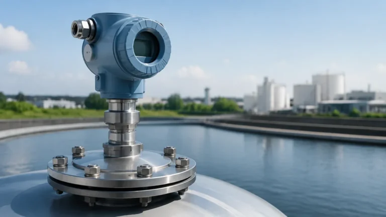
Differential Pressure Measuring Instrument
Differential Pressure Measuring Instrument
Differential pressure (DP) measurement is one of the most versatile and widely adopted technologies in industrial process control. While it is fundamentally designed to measure the difference in pressure between two points, its application extends far beyond simple pressure monitoring. In the context of level measurement, a differential pressure measuring instrument serves as a reliable tool for determining the height of liquids in both open and pressurized vessels.
By leveraging the principles of hydrostatics, these instruments provide accurate data essential for water treatment, chemical processing, and oil and gas operations. This guide explores the engineering principles, selection criteria, and installation best practices for differential pressure measuring instruments in industrial environments.
Understanding the Measurement Principle
The operation of a differential pressure measuring instrument for level applications is based on the relationship between the height of a liquid column and the hydrostatic pressure it exerts at the base of a tank. This is governed by the formula:
P = ρ × g × h
Where:
- P is the hydrostatic pressure.
- ρ (rho) is the density of the liquid (kg/m³).
- g is the acceleration due to gravity (approximately 9.81 m/s²).
- h is the height of the liquid column (m).
Open Tank Measurement
In an atmospheric (open) tank, the "low-pressure" side of the instrument is vented to the atmosphere. The "high-pressure" side is connected to the bottom of the tank. As the liquid level rises, the hydrostatic pressure increases linearly. The instrument measures this pressure relative to the atmosphere to calculate the level.
Closed and Pressurized Tank Measurement
In pressurized vessels, the pressure above the liquid (the gas space or "blanket" pressure) adds to the hydrostatic pressure at the bottom. To isolate the pressure caused only by the liquid height, a differential pressure measuring instrument is used to subtract the head pressure from the total pressure at the bottom. The high-pressure (HP) port is connected to the bottom of the vessel, and the low-pressure (LP) port is connected to the top of the vessel. The resulting differential pressure (ΔP) is directly proportional to the liquid level, regardless of changes in the vessel’s internal pressure.
Key Components of a Differential Pressure Measuring Instrument
A modern electronic DP transmitter consists of several critical components that ensure accuracy and long-term stability:
1. Sensing Element: Usually a flexible diaphragm (made of stainless steel, Hastelloy, or Monel) that deflects under pressure. This deflection is converted into an electrical signal via capacitive, piezoresistive, or inductive sensors.
2. Process Flanges/Adapters: These provide the physical connection to the process piping or vessel. They must be rated for the maximum working pressure of the system.
3. Electronic Module: This component processes the raw sensor signal, performs temperature compensation, and converts the data into a standard output signal, such as 4-20mA with HART, Modbus, or Foundation Fieldbus.
4. Display/Interface: Local indicators allow technicians to view real-time readings and perform basic configuration in the field.
Selection Criteria for Industrial Applications
Choosing the right differential pressure measuring instrument requires a detailed understanding of the process media and environmental conditions. Engineers should evaluate the following factors:
Material Compatibility
The wetted parts, particularly the diaphragms, must be resistant to the process fluid. For general water treatment, 316L stainless steel is standard. However, for aggressive chemicals or seawater, materials like Tantalum or PTFE coatings may be necessary.
Pressure and Temperature Ratings
The instrument must withstand the maximum static pressure of the vessel. Furthermore, temperature fluctuations can affect the density of the liquid and the physical properties of the sensor. High-temperature applications may require remote seals and capillary tubing to protect the transmitter electronics from heat.
Selection Table: DP Transmitter vs. Application
| Feature | Standard DP Transmitter | Remote Seal DP Transmitter | Multivariable DP Transmitter |
| :— | :— | :— | :— |
| Best For | Clean liquids, low viscosity | Corrosive, viscous, or hot fluids | Combined level and flow monitoring |
| Installation | Direct or via impulse lines | Capillary tubes to vessel | Integrated manifold |
| Maintenance | Moderate (impulse line cleaning) | Low (sealed system) | Moderate |
| Accuracy | High (0.075% to 0.04% span) | Good (affected by capillary length) | High |
For a comprehensive look at available hardware and technical specifications, you may Review product options and application support on our Main Page.
Installation and Commissioning Guidelines
Correct installation is the most significant factor in the performance of a differential pressure measuring instrument. Errors in mounting often lead to "zero drift" or sluggish response times.
Impulse Line Configuration
Impulse lines are the small-bore pipes that connect the process to the transmitter.
- Slope: Lines should be sloped at least 1:12 (approx. 8%) to ensure that gas bubbles can rise back into the tank (for liquid service) or condensate can drain back (for gas service).
- Wet Leg vs. Dry Leg: In pressurized tanks with condensing vapors, the low-pressure impulse line may fill with liquid. This is called a "wet leg." The weight of this liquid column must be mathematically accounted for during calibration (zero suppression). If the vapor does not condense, a "dry leg" is used.
Manifold Valves
A 3-way or 5-way valve manifold should always be installed between the process and the instrument. This allows the transmitter to be isolated, vented, or equalized for zero-point calibration without shutting down the entire process.
Mounting Position
The transmitter should ideally be mounted below the process taps for liquid measurement to keep the impulse lines filled with fluid. If mounted above the taps, air traps must be avoided, and the system may require constant venting.

Limitations and Mitigation Strategies
While highly reliable, the differential pressure measuring instrument has inherent limitations that engineers must manage:
1. Density Sensitivity: Since DP instruments measure mass-derived pressure, any change in liquid density (caused by temperature or concentration changes) will result in a level error.
* *Mitigation:* Use a multivariable transmitter that includes a temperature sensor to calculate real-time density compensation.
2. Impulse Line Clogging: In applications with suspended solids or slurries, impulse lines can clog.
* *Mitigation:* Use flush-mounted diaphragm seals (remote seals) instead of open impulse lines to prevent the process media from entering the instrument internals.
3. Static Pressure Effects: Very high operating pressures can cause a slight shift in the diaphragm's zero point.
* *Mitigation:* Perform "zeroing" of the instrument at the actual operating static pressure of the vessel using the manifold equalization valve.
Comparison with Other Technologies
In the modern industrial landscape, DP measurement often competes with Radar and Ultrasonic technologies. Understanding when to use a differential pressure measuring instrument is key to cost-effective engineering.
- DP vs. Radar: Radar is non-contact and unaffected by density changes, making it superior for fluctuating densities. However, DP is often more cost-effective for high-pressure vessels and is not affected by surface foam or internal tank obstructions that might interfere with radar signals.
- DP vs. Ultrasonic: Ultrasonic sensors are limited by vacuum conditions and heavy vapor layers. DP transmitters excel in high-pressure and high-vacuum environments where sound waves cannot propagate effectively.
Frequently Asked Questions (FAQs)
Q: How often should a differential pressure measuring instrument be calibrated?
A: Most modern smart transmitters are stable for 5 to 10 years. However, regulatory requirements or critical safety loops may dictate annual or biennial calibration checks.
Q: Can a DP transmitter measure the level of an interface between two liquids?
A: Yes. If the two liquids have different densities (e.g., oil and water), a DP instrument can measure the interface level, provided the total liquid height remains constant or is measured by a second instrument.
Q: What is zero suppression and zero elevation?
A: Zero suppression is used when the transmitter is mounted below the tank bottom, creating a constant positive pressure at zero level. Zero elevation is used when a "wet leg" creates a constant negative pressure on the low-pressure side relative to the high-pressure side.
Q: Does the size of the tank affect the DP transmitter selection?
A: The physical size of the tank does not affect the transmitter's accuracy, but the total height determines the required pressure range (span). A 2-meter (6.5 ft) tank requires a much more sensitive sensor than a 20-meter (65.6 ft) silo.
Conclusion
The differential pressure measuring instrument remains a fundamental tool in the arsenal of process engineers. Its ability to provide precise level data in pressurized environments, combined with its mechanical robustness, ensures its continued relevance in industrial automation. By carefully considering material compatibility, density variations, and proper impulse line installation, users can achieve highly accurate and maintenance-free level measurement for years of service.
For technical assistance or to explore our full range of industrial level sensors, visit our Main Page to find the ideal solution for your specific application requirements.
Download Differential Pressure Measuring Instrument as a PDF