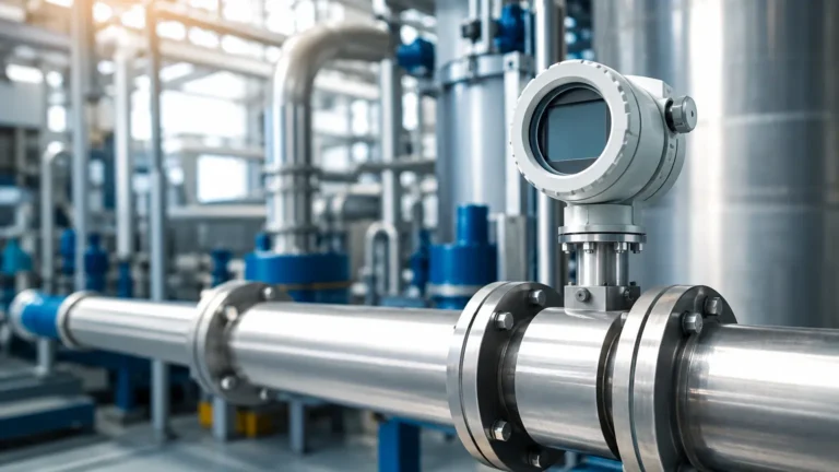
Ph Sensor Transmitter
Ph Sensor Transmitter
In the landscape of industrial process control, the ability to monitor and manage the chemical properties of liquids is as critical as measuring their physical volume. A ph sensor transmitter serves as the bridge between a raw electrochemical reaction and a digital control system. While level measurement instruments—such as those found on the Main Page of industrial instrumentation providers—ensure that tanks do not overflow or run dry, the pH sensor transmitter ensures that the fluid within those tanks remains within specified chemical boundaries.
This article provides a comprehensive technical guide to the selection, installation, and maintenance of pH sensor transmitters, focusing on their integration into broader industrial automation frameworks alongside level measurement solutions.
Fundamental Principles of pH Measurement
To understand the function of a ph sensor transmitter, one must first understand the electrochemical process it monitors. The pH value is a measure of the hydrogen ion activity in a solution, defined mathematically as the negative logarithm of the hydrogen ion concentration.
The Nernst Equation
The operational core of most industrial pH sensors is the Nernst Equation. This equation describes the relationship between the potential of an electrochemical cell and the concentration of the ions in the solution. In practical terms, a pH electrode generates a millivolt (mV) signal that varies linearly with the pH of the liquid. At a neutral pH of 7.0, the theoretical output of the sensor is 0 mV. As the solution becomes more acidic (pH < 7), the voltage becomes positive; as it becomes more alkaline (pH > 7), the voltage becomes negative.
Signal Conversion
The raw signal from a pH electrode is characterized by extremely high impedance, often exceeding 100 MΩ. This makes the signal highly susceptible to electromagnetic interference and signal degradation over long cable distances. The primary role of the ph sensor transmitter is to receive this high-impedance mV signal, amplify it, and convert it into a robust industrial standard, such as a 4-20mA current loop, RS485 Modbus, or Foundation Fieldbus. This conversion allows the data to be transmitted reliably to a Programmable Logic Controller (PLC) or Distributed Control System (DCS).
Components of an Industrial pH Sensor Transmitter System
A complete measurement loop typically consists of three primary components: the sensing electrode, the reference electrode (often combined into a single "combination electrode"), and the transmitter unit.
1. The Glass Electrode: This contains a specialized pH-sensitive glass membrane. When immersed in a liquid, a hydrated layer forms on the outer surface of the glass, allowing hydrogen ions to exchange and create a potential difference relative to the internal buffer solution.
2. The Reference Electrode: To measure the potential of the glass electrode, a stable reference point is required. The reference electrode provides a constant potential regardless of the pH of the medium, typically using a silver/silver chloride (Ag/AgCl) system and a liquid junction.
3. Temperature Compensation (ATC): Because the mV output of the electrode is temperature-dependent (as defined by the Nernst Equation), most modern systems include a Resistance Temperature Detector (RTD), such as a Pt100 or Pt1000, to provide Automatic Temperature Compensation (ATC).
4. The Transmitter: This is the electronic assembly that houses the display, user interface, and signal processing hardware. It performs the calibration math, applies temperature corrections, and drives the output signal.
Selection Criteria for Process Applications
Choosing the correct ph sensor transmitter requires an analysis of the process environment. The following table outlines selection parameters based on common industrial scenarios:
| Application Requirement | Recommended Sensor/Transmitter Features | Key Consideration |
| :— | :— | :— |
| Wastewater Treatment | Combination electrode with large surface area junction | Resistance to fouling and clogging |
| Chemical Processing | PTFE or ceramic junctions; high-pressure rated housings | Chemical compatibility with acids/bases |
| High-Temperature Steam | Specialized high-temperature glass; pressurized reference | Thermal stability up to 130°C (266°F) |
| Pure Water (Power Plants) | Flow-through cells with low-impedance glass | Minimizing static charge interference |
| Remote Monitoring | RS485 Modbus or HART-enabled transmitters | Integration with long-distance telemetry |
When integrating these sensors into a facility that already utilizes advanced level measurement, such as radar or ultrasonic sensors available at the Welk Main Page, it is essential to ensure that the transmitter's communication protocol is compatible with the existing control architecture.
Integration with Level Control Systems
In many industrial applications, pH measurement and level measurement are intrinsically linked. For example, in a neutralization tank, a hydrostatic level transmitter or an ultrasonic level sensor monitors the volume of the effluent, while the ph sensor transmitter monitors the acidity.
Automated Dosing
The PLC uses the level data to determine the total volume of liquid and the pH data to determine the concentration of reagents needed. If the level is high and the pH is out of spec, the system triggers dosing pumps to inject acid or caustic soda. Without accurate data from both the level meter and the pH transmitter, the dosing process could be inefficient or even dangerous, leading to tank overflows or chemical imbalances.
Combined Data Logging
Modern industrial facilities often utilize multi-parameter controllers that can accept inputs from both level sensors and pH transmitters. This allows for unified data logging, which is essential for regulatory compliance in industries like food and beverage or pharmaceutical manufacturing.
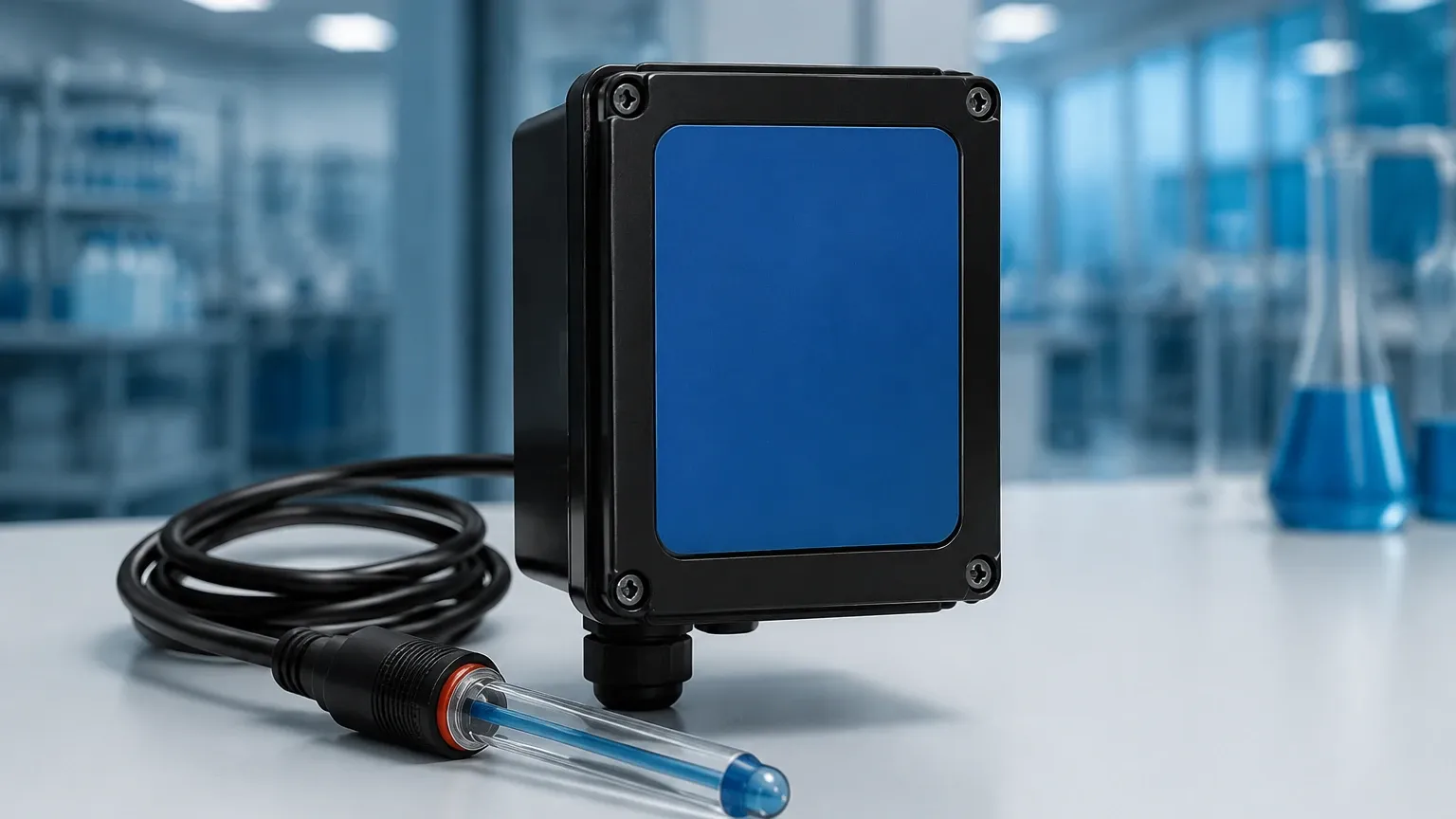
Installation and Mounting Guidelines
The physical installation of a ph sensor transmitter significantly impacts its accuracy and lifespan. Unlike level meters, which are often non-contact (like radar), pH sensors must be in direct contact with the process medium.
Mounting Configurations
* Immersion Mounting: Used for open tanks or pits. The sensor is mounted on the end of a pipe (submersion assembly) and lowered into the liquid. It is vital to ensure the cable entry is sealed against moisture.
* In-line Mounting: The sensor is installed directly into a process pipe using a T-fitting. This allows for real-time monitoring of flowing liquids but requires a bypass line for maintenance.
* Retractable Assemblies: These allow the sensor to be removed from a pressurized pipe or tank for cleaning and calibration without shutting down the process. This is the preferred method for critical 24/7 operations.
Positioning Considerations
* Angle of Installation: Sensors should generally be installed at an angle of at least 15° above the horizontal to ensure that the internal electrolyte stays in contact with the glass membrane and to prevent air bubbles from being trapped.
* Flow Velocity: While some flow is necessary to ensure a representative sample, excessive velocity can cause "streaming potentials" or physical erosion of the glass membrane.
Calibration and Maintenance Protocols
Unlike a radar level meter, which may operate for years with minimal drift, a ph sensor transmitter requires regular calibration. The electrochemical nature of the sensor means that the glass membrane and reference junction will inevitably age.
The Calibration Process
Calibration should be performed using standard buffer solutions, typically at pH 4.0, 7.0, and 10.0.
1. Zero Point Calibration: Performed at pH 7.0. This accounts for the "isopotential point" of the electrode.
2. Slope Calibration: Performed at a second pH point (e.g., pH 4.0 for acidic processes). This determines the efficiency of the electrode. A new electrode should have a slope between 95% and 102% of the theoretical Nernstian value (59.16 mV/pH at 25°C).
Cleaning Procedures
Fouling is the most common cause of measurement error.
* Organic coatings: Clean with a mild detergent or isopropyl alcohol.
* Inorganic scale (Calcium): Use a 5% Hydrochloric acid (HCl) soak.
* Oil and Grease: Use specialized surfactants.
Limitations and Common Challenges
While highly effective, the ph sensor transmitter has inherent limitations that engineers must account for during the design phase:
* Lifespan: Most industrial pH electrodes have a lifespan of 6 to 18 months, depending on the temperature and chemical aggressiveness of the environment.
* Pressure Sensitivity: High process pressures can force the process liquid into the reference junction, poisoning the electrode. In these cases, a pressurized reference electrode or a solid-state reference is required.
* Sodium Error: In extremely high pH environments (pH > 12), the sensor may respond to sodium ions as if they were hydrogen ions, leading to a lower-than-actual pH reading.
* Dehydration: If a pH electrode is allowed to dry out, the hydrated layer on the glass membrane will collapse. While some sensors can be regenerated by soaking in a storage solution (typically 3M KCl), others may be permanently damaged.
Frequently Asked Questions (FAQ)
Q: How far can the ph sensor transmitter be located from the electrode?
A: If using a raw analog signal (mV), the distance should be kept under 10-15 meters to avoid noise. However, if using a "smart" sensor with an integrated pre-amplifier or a digital output (like Modbus), the distance can be extended to hundreds of meters.
Q: Can I use a ph sensor transmitter to measure the pH of non-aqueous liquids like oil?
A: Standard pH sensors require an aqueous (water-based) medium to establish an electrical circuit through the junction. Measuring pH in non-aqueous liquids requires specialized electrodes and often involves complex sampling techniques.
Q: Why does my pH reading drift even after calibration?
A: Drift is often caused by a clogged reference junction or temperature fluctuations that exceed the compensation capabilities of the transmitter. Ensure the junction is clean and that the temperature sensor is functioning correctly.
Q: How does a ph sensor transmitter handle ground loops?
A: High-quality transmitters feature galvanic isolation between the sensor input and the analog output. This prevents electrical noise from the process tank (common in metal tanks with pumps) from interfering with the sensitive mV measurement.
For engineers seeking to build a robust monitoring system, combining chemical analysis via a ph sensor transmitter with reliable physical measurement from the Main Page ensures total process visibility. By adhering to strict installation and calibration schedules, these instruments provide the data necessary for safe and efficient industrial operations.