Inline Conductivity Sensor
Inline Conductivity Sensor
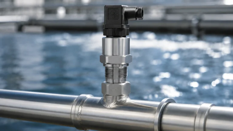
In industrial process control, the ability to monitor the ionic concentration of a liquid in real-time is critical for maintaining product quality, ensuring equipment longevity, and optimizing chemical dosing. An inline conductivity sensor serves as the primary tool for this task, providing continuous measurements of a solution's ability to conduct an electrical current. This measurement is a direct proxy for the total dissolved solids (TDS) or the concentration of electrolytes within a process stream.
For engineers and plant managers, selecting the correct inline conductivity sensor requires a deep understanding of the underlying measurement principles, the chemical environment of the application, and the physical constraints of the piping system. This guide provides a technical overview of conductivity technology, selection criteria, and installation best practices for industrial environments.
Measurement Principles of Conductivity
Conductivity is defined as the ability of a material to conduct electric current. In liquids, this current is carried by ions (such as salts, acids, or bases) rather than electrons. The standard unit of measurement is Siemens per meter (S/m), though in industrial applications, it is more commonly expressed in microsiemens per centimeter (µS/cm) or millisiemens per centimeter (mS/cm).
The Role of the Cell Constant (K)
The geometry of the sensor significantly impacts the measurement. The cell constant ($K$) is the ratio of the distance ($d$) between the electrodes to the cross-sectional area ($A$) of the liquid between them ($K = d/A$).
* Low Cell Constants (e.g., $K=0.01$ or $0.1$): Used for high-purity water where the distance between electrodes is small or the surface area is large.
* High Cell Constants (e.g., $K=1.0$ or $10.0$): Used for concentrated chemicals or wastewater where the electrodes are spaced further apart to prevent short-circuiting or to handle high ionic density.
Contacting vs. Inductive Measurement
There are two primary methods used by an inline conductivity sensor to determine the electrolytic conductivity of a fluid:
1. Contacting Conductivity: This method involves two or more electrodes (usually stainless steel, graphite, or titanium) that come into direct contact with the process fluid. An alternating voltage is applied between the electrodes, and the resulting current is measured. While highly accurate for low-conductivity applications like deionized water, these sensors are susceptible to electrode fouling and polarization.
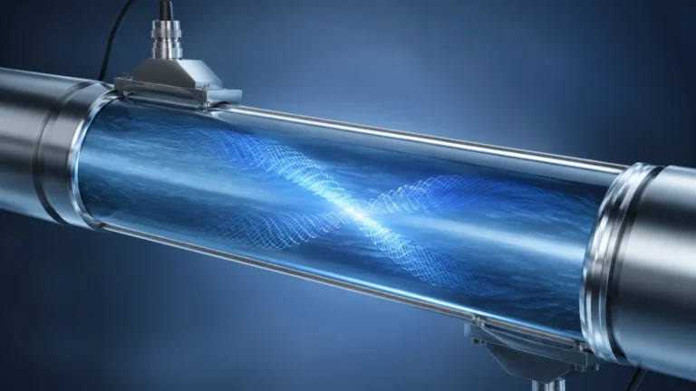
2. Inductive (Toroidal) Conductivity: This method uses two wire-wound metal toroids encased in a plastic body (such as PEEK or PFA). One coil acts as a transmitter, inducing an alternating current in the surrounding liquid. The second coil acts as a receiver, measuring the magnitude of this current. Because the sensor does not have metal electrodes in contact with the fluid, it is immune to fouling and corrosion, making it ideal for harsh chemical processes.
Types of Inline Conductivity Sensors
Choosing the right sensor type depends on the expected conductivity range and the cleanliness of the fluid.
Two-Electrode Sensors
Two-electrode sensors are the traditional choice for high-purity water applications. They are simple and offer high precision at very low conductivity levels (0.055 µS/cm to 200 µS/cm). However, they are prone to "polarization error" at higher conductivities, where ions build up near the electrode surface and create a false resistance.
Four-Electrode Sensors
To overcome polarization and the effects of minor scaling, four-electrode sensors utilize two drive electrodes and two sensing electrodes. The drive electrodes create the current, while the sensing electrodes measure the voltage drop. This design allows the sensor to maintain accuracy over a much wider range (from 10 µS/cm to 1,000 mS/cm) and is more resilient to electrode coating.
Toroidal (Electrodeless) Sensors
Toroidal sensors are the workhorses of the chemical industry. Since there are no electrodes to corrode or coat, they are used for measuring high-concentration acids, bases, and slurries. They are typically used for ranges between 500 µS/cm and 2,000 mS/cm. Their robust design significantly reduces maintenance requirements in demanding applications.
Key Evaluation Criteria for Industrial Selection
When evaluating an inline conductivity sensor for a specific project, engineers must confirm several technical parameters to ensure long-term reliability.
Chemical Compatibility
The wetted materials of the sensor must withstand the process media. For contacting sensors, 316L Stainless Steel is standard, but Titanium or Monel may be required for aggressive fluids. For toroidal sensors, the outer casing (PEEK, PP, or PFA) must be checked against the chemical concentration and temperature. For a broader range of industrial instrumentation and material options, engineers can Review product options and application support to match sensor specifications with specific chemical profiles.
Temperature Compensation
Conductivity is highly temperature-dependent; typically, conductivity increases by about 2% for every 1°C increase in temperature. Most industrial sensors include an internal temperature element (like a Pt100 or Pt1000) to provide Temperature Compensated Conductivity, usually referenced to 25°C. Selecting a sensor with a fast-responding temperature element is vital for processes with fluctuating thermal loads.
Pressure and Mounting
Inline sensors must be rated for the maximum process pressure, often up to 10 bar (145 psi) or higher for high-pressure boiler loops. Mounting options include NPT threads, flange mounts, or hygienic Tri-Clamp fittings for food and pharmaceutical applications.
Selection Table: Technology Comparison
| Feature | 2-Electrode Contacting | 4-Electrode Contacting | Inductive (Toroidal) |
| :— | :— | :— | :— |
| Best Range | 0.01 – 200 µS/cm | 10 µS/cm – 1,000 mS/cm | 500 µS/cm – 2,000 mS/cm |
| Sensitivity | Extremely High | Moderate | Low (at low conductivity) |
| Fouling Resistance | Low | Moderate | High |
| Common Use | Ultrapure Water, RO | Cooling Towers, General Process | Acids, Brines, Slurries |
| Maintenance | High (Cleaning/Cal) | Moderate | Very Low |
Installation Considerations
To achieve accurate and repeatable results, the physical installation of an inline conductivity sensor must follow specific engineering guidelines:
1. Full Pipe Requirement: The sensor must be installed in a location where the pipe is always full of liquid. Entrained air or half-full pipes will result in erratic and inaccurately low readings.
2. Flow Direction: For contacting sensors, the flow should ideally be directed into the electrode opening to ensure constant refreshing of the sample and to prevent the accumulation of debris.
3. Avoidance of Bubbles: Sensors should not be installed at the highest point of a piping system where air pockets collect, nor should they be placed immediately downstream of a pump where cavitation might occur.
4. Orientation: In horizontal pipes, sensors should be installed from the side (3 o'clock or 9 o'clock position) rather than the top or bottom. Top mounting risks air pockets, while bottom mounting risks sediment accumulation.
5. Interference (Toroidal Only): Inductive sensors generate a magnetic field. If installed too close to a metallic pipe wall, the field can be distorted, leading to measurement errors. Manufacturers typically specify a minimum "wall clearance" (e.g., 20 mm to 50 mm) or provide calibration factors for installation in small-diameter metal pipes.

Common Risks and Limitations
While inline conductivity sensors are robust, several factors can compromise their performance:
* Polarization: Occurs in 2-electrode sensors when high current densities cause ions to migrate, creating a capacitive layer that increases apparent resistance.
* Coating and Scaling: In contacting sensors, the buildup of calcium carbonate, oils, or biological growth on the electrodes effectively changes the cell constant, leading to a drift in readings. Regular cleaning with a mild acid or solvent is often required.
* Cable Interference: Conductivity signals, especially from high-impedance contacting sensors, are sensitive to electromagnetic interference (EMI). Using shielded cables and maintaining separation from high-voltage power lines is essential.
* Non-Specific Measurement: Conductivity measures *all* ions. It cannot distinguish between sodium chloride and sulfuric acid. If the process involves multiple changing variables, conductivity may not be sufficient on its own to determine the concentration of a specific component.
Practical Application Examples
Water Treatment and Reverse Osmosis
In RO systems, inline conductivity sensors are placed at the feed, permeate, and concentrate stages. By comparing the feed conductivity to the permeate conductivity, the system calculates the "rejection rate," which is a primary indicator of membrane health.
CIP (Clean-in-Place) Systems
In the food and beverage industry, conductivity sensors are used to detect the interface between water and cleaning chemicals (like caustic soda). This allows for automated switching of valves, reducing chemical waste and ensuring that no cleaning agents remain in the production line.
Boiler Blowdown Control
As water evaporates in a boiler, the concentration of dissolved solids increases. High conductivity can lead to foaming and carryover, damaging turbines. An inline sensor triggers a blowdown valve when conductivity exceeds a set limit, maintaining safe operating conditions while minimizing heat loss.
Conclusion and Next Steps
An inline conductivity sensor is an essential component for automated process control, but its effectiveness is entirely dependent on matching the technology to the application environment. For clean, low-conductivity water, contacting sensors remain the gold standard. For aggressive, high-concentration chemicals or fluids prone to scaling, toroidal sensors offer a superior, low-maintenance solution.
Before finalizing a specification, project teams should confirm the maximum expected conductivity range, the presence of any abrasive or coating agents, and the required communication protocol (e.g., 4-20mA, Modbus, or HART). For comprehensive support in integrating these sensors into a broader industrial automation framework, including level and flow measurement, users are encouraged to visit the Welk Main Page for detailed technical documentation and product selection tools.
Frequently Asked Questions (FAQ)
Q: How often should an inline conductivity sensor be calibrated?
A: Calibration frequency depends on the process. In clean water applications, once or twice a year may suffice. In fouling environments, monthly checks are recommended. Toroidal sensors generally require less frequent calibration than contacting sensors.
Q: Can I use a conductivity sensor to measure the concentration of a specific acid?
A: Yes, provided the solution is a binary mixture (e.g., only water and sulfuric acid). Most modern transmitters include pre-programmed concentration curves for common chemicals like HCl, NaOH, and $H_2SO_4$.
Q: What is the difference between conductivity and TDS?
A: Conductivity measures the electrical current-carrying capacity. TDS (Total Dissolved Solids) is a mass-based measurement. TDS is usually estimated by multiplying conductivity by a factor (typically between 0.5 and 0.7), depending on the specific ions present in the water.
Q: How do I clean a coated conductivity sensor?
A: For mineral scale, a 5% hydrochloric acid solution is usually effective. For oils or greases, a mild detergent or isopropyl alcohol can be used. Always rinse thoroughly with deionized water before returning the sensor to service.