Ultrasonic Flow Meter Principle
Ultrasonic Flow Meter Principle
Ultrasonic flow measurement has become a cornerstone of modern industrial process control due to its non-invasive nature and high reliability. Unlike mechanical meters that rely on moving parts subject to wear, ultrasonic flow meters utilize acoustic signals to determine the velocity of a fluid within a closed conduit. Understanding the ultrasonic flow meter principle is essential for engineers and technicians tasked with selecting the right instrumentation for water treatment, chemical processing, and oil and gas applications.
As a professional manufacturer of industrial measurement instruments, Welk provides advanced technology solutions that integrate seamlessly into complex automation systems. While many facilities focus on level measurement, the integration of flow data is critical for comprehensive mass balance and process efficiency. For those looking to optimize their entire measurement suite, you can Review product options and application support to find compatible instrumentation for your specific industrial environment.
The Fundamental Ultrasonic Flow Meter Principle
There are two primary methods used in ultrasonic flow measurement: Transit-time and Doppler shift. Both rely on the propagation of ultrasonic waves—typically at frequencies between 0.5 MHz and 4 MHz—through the fluid, but they utilize different physical phenomena to calculate flow rate.
1. Transit-Time Method
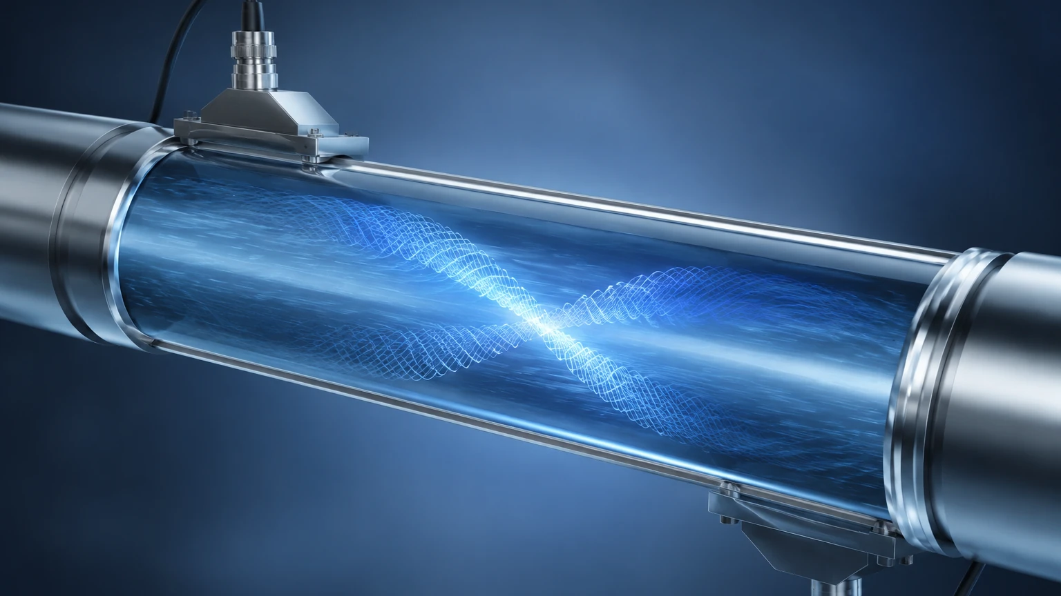
The transit-time ultrasonic flow meter principle is based on the difference in the time it takes for an ultrasonic pulse to travel between two transducers. One transducer is located upstream and the other downstream.
When the fluid is stationary, the time taken for a signal to travel from the upstream transducer to the downstream transducer ($t_{ab}$) is identical to the time taken from downstream to upstream ($t_{ba}$). However, when the fluid is moving, the pulse traveling with the flow (downstream) moves faster, while the pulse traveling against the flow (upstream) is slowed down.
The relationship can be expressed mathematically:
* Downstream time: $t_{ab} = L / (C + V \cos \theta)$
* Upstream time: $t_{ba} = L / (C – V \cos \theta)$
Where:
* L is the distance between transducers.
* C is the speed of sound in the fluid.
* V is the velocity of the fluid.
* θ is the angle of the signal path relative to the flow direction.
By measuring the time difference ($Δt = t_{ba} – t_{ab}$), the electronics can calculate the fluid velocity (V). Because this method relies on a clear signal path, it is best suited for clean liquids with minimal suspended solids or gas bubbles.
2. Doppler Effect Method
The Doppler ultrasonic flow meter principle utilizes the frequency shift of an ultrasonic signal reflected off moving discontinuities within the fluid. These discontinuities can be suspended solids, entrained gas bubbles, or even turbulence in the flow stream.
When a transducer transmits a signal of a known frequency ($f_t$) into the moving fluid, the signal reflects off the particles moving at velocity (V). The reflected frequency ($f_r$) received by the sensor is shifted based on the Doppler effect:
$$Δf = f_r – f_t = 2 f_t (V / C) \cos θ$$
Unlike the transit-time method, the Doppler method requires the presence of particles or bubbles to function. It is the preferred choice for wastewater, slurries, and aerated liquids where a transit-time signal would be attenuated or blocked.
Technical Comparison and Selection Criteria
Choosing between transit-time and Doppler technologies depends entirely on the fluid characteristics and the required accuracy. The following table provides a practical selection guide for industrial applications.
| Feature | Transit-Time Ultrasonic Meter | Doppler Ultrasonic Meter |
| :— | :— | :— |
| Fluid Type | Clean liquids, deionized water, oils | Slurries, wastewater, aerated liquids |
| Suspended Solids | < 2% by volume | > 100 ppm (usually > 0.5% to 2%) |
| Accuracy | 0.5% to 1.0% of velocity | 1.0% to 5.0% of velocity |
| Pipe Size Range | 10 mm to 5,000 mm | 25 mm to 5,000 mm |
| Sensitivity to Bubbles | High (causes signal loss) | Required for operation |
| Flow Direction | Bi-directional | Bi-directional |
When evaluating these systems, engineers must also consider the pipe material. Ultrasonic signals travel efficiently through metal (carbon steel, stainless steel) and most plastics (PVC, PE), but highly porous materials like concrete or unlined cast iron can scatter the signal, reducing measurement reliability.
Installation Considerations and Mounting Methods
The performance of an ultrasonic flow meter is heavily dependent on the installation environment. Because the ultrasonic flow meter principle relies on stable acoustic paths and predictable flow profiles, several factors must be addressed during setup.
Straight Pipe Requirements
To ensure a fully developed laminar flow profile, the meter must be installed in a section of pipe with sufficient straight runs. Standard engineering practice recommends:
* Upstream: Minimum 10D (10 times the pipe diameter) of straight pipe after elbows or valves.
* Downstream: Minimum 5D of straight pipe before the next fitting.
If the flow is highly turbulent or swirling, longer upstream runs or flow conditioners may be necessary to maintain accuracy.
Transducer Mounting Configurations
There are three common ways to mount external clamp-on transducers:
1. V-Method: The transducers are mounted on the same side of the pipe. The signal bounces off the opposite wall. This is the standard method for pipe diameters ranging from 25 mm to 400 mm (1 to 16 inches).
2. Z-Method: The transducers are mounted on opposite sides of the pipe. The signal crosses the pipe once. This is used for large pipes (over 400 mm) or when the fluid is slightly attenuating.
3. W-Method: The signal bounces three times before reaching the receiver. This is used for very small pipes (under 50 mm) to increase the transit time and improve resolution.
Acoustic Coupling
For clamp-on meters, an acoustic coupling compound (grease or gel) must be applied between the transducer face and the pipe surface. This eliminates air gaps, which would otherwise reflect the ultrasonic energy and prevent it from entering the pipe wall.
Limitations and Operational Risks
While ultrasonic meters offer significant advantages—such as no pressure drop and no risk of leakage—they are not universal solutions. Understanding their limitations is vital for long-term reliability.
* Fluid Aeration: Excessive air or gas bubbles in a transit-time meter will scatter the ultrasonic beam, leading to a "signal loss" error. In such cases, a Doppler meter or a different technology like a magnetic flow meter may be required.
* High Viscosity: Extremely viscous fluids can affect the flow profile, requiring specialized Reynolds number compensation within the meter's electronics.
* Temperature Extremes: Standard transducers are often limited to temperatures below 150°C (302°F). High-temperature applications require specialized transducers and mounting hardware to protect the piezoelectric elements.
* Pipe Scaling: Internal buildup or scaling can change the internal diameter of the pipe and attenuate the signal, leading to measurement drift over time.
For complex industrial environments where both flow and level must be monitored—such as chemical storage tanks or open-channel flumes—consulting with a professional manufacturer like Welk ensures that the selected instrumentation matches the physical properties of the medium. You can explore the Main Page for a broader view of how ultrasonic technology is applied to level and process monitoring.
Frequently Asked Questions (FAQ)
Can ultrasonic flow meters measure steam?
Generally, no. Standard ultrasonic flow meters are designed for liquids. While specialized high-temperature gas ultrasonic meters exist for steam, they operate on different frequency ranges and are significantly more complex and expensive than liquid meters.
Does pipe material affect the ultrasonic flow meter principle?
Yes. The speed of sound through the pipe wall varies by material. The meter's electronics must be programmed with the correct pipe material, wall thickness, and liner material (if any) to accurately calculate the refraction angles of the ultrasonic signal.
Is calibration required for clamp-on meters?
While the electronic components are calibrated at the factory, the overall system accuracy depends on the user entering correct pipe dimensions. Field verification using a portable master meter is often recommended for critical applications to ensure the installation geometry is correct.
How does fluid temperature affect accuracy?
The speed of sound in a liquid changes with temperature. Most modern ultrasonic flow meters include temperature compensation algorithms or allow for an external temperature sensor input to adjust the calculation in real-time.
Conclusion
The ultrasonic flow meter principle offers a versatile, non-intrusive solution for a wide range of industrial applications. By selecting between transit-time and Doppler methods based on fluid clarity and following strict installation guidelines regarding pipe runs and mounting, engineers can achieve high-precision flow data without interrupting process operations. Whether managing water resources or monitoring chemical throughput, the correct application of ultrasonic technology is a key driver of operational reliability and cost-effectiveness.