Level Sensor Symbol
Level Sensor Symbol
In industrial automation and process control, clear communication between engineers, technicians, and operators is essential for the safety and efficiency of a plant. The primary tool for this communication is the Piping and Instrumentation Diagram (P&ID). Central to these diagrams is the level sensor symbol, a standardized graphical representation that identifies the type, function, and location of level measurement instruments.
Whether you are designing a new water treatment facility or maintaining a complex chemical reactor, understanding the nuances of these symbols is critical. This guide explores the standardized symbology used for level measurement, the underlying principles of the instruments they represent, and practical considerations for selection and installation.
Understanding the Role of Level Sensor Symbols in Process Engineering
A level sensor symbol is more than just a drawing; it is a shorthand for a set of technical specifications. Most industrial standards follow the ISA-5.1 (International Society of Automation) conventions. These symbols provide immediate information regarding:
1. The Measured Variable: In this case, "L" for Level.
2. The Function of the Instrument: Whether it is a transmitter (T), an indicator (I), a controller (C), or a switch (S).
3. The Location: Whether the device is field-mounted, accessible in a primary control room, or hidden behind a panel.
4. The Loop Number: A unique identifier that links the physical device to the plant's documentation.
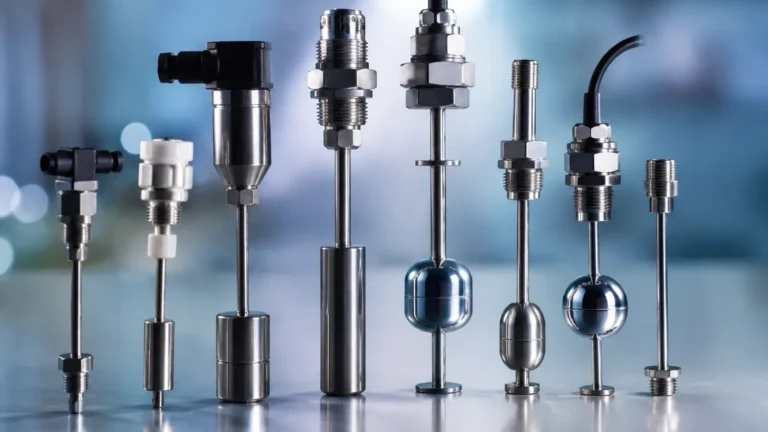
For instance, a circle containing "LT" represents a Level Transmitter, which provides continuous measurement. Conversely, a circle containing "LSH" represents a Level Switch High, a device used for point level detection to prevent overfills. For high-quality hardware to match these designs, engineers often rely on professional Level Switches to ensure reliable discrete signaling.
Measurement Principles: From Continuous Sensors to Level Switches
Before selecting a level sensor symbol for a schematic, it is vital to understand how the physical instrument operates. Level measurement is generally divided into two categories: continuous measurement and point level detection.
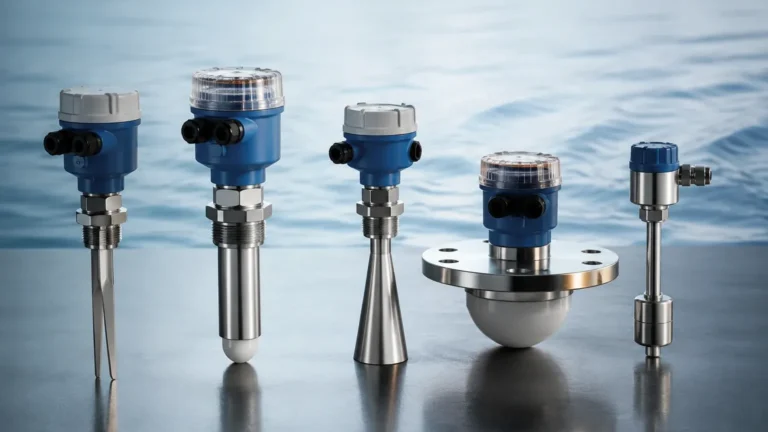
Radar Level Measurement
Radar level meters use Time-of-Flight (ToF) technology. They emit high-frequency microwave pulses (typically in the 26 GHz or 80 GHz range) that travel to the surface of the medium and reflect back. The distance is calculated based on the time it takes for the pulse to return. This technology is non-contact and highly accurate, making it ideal for corrosive or high-temperature liquids.
Ultrasonic Level Sensors
Similar to radar, ultrasonic sensors use sound waves. A transducer emits an ultrasonic pulse that bounces off the liquid surface. While cost-effective for water treatment and simple storage tanks, ultrasonic sensors can be affected by foam, heavy vapors, or significant temperature fluctuations that alter the speed of sound.
Hydrostatic Level Transmitters
These sensors measure the pressure exerted by a liquid column. Based on the formula $P = \rho gh$ (where $P$ is pressure, $\rho$ is density, $g$ is gravity, and $h$ is height), the sensor determines the level. These are typically submerged or mounted at the bottom of a tank.
Level Switches (Point Level Detection)
Unlike transmitters that provide a 4-20mA or digital output of the exact level, level switches are designed to trigger at a specific point. Common types include:
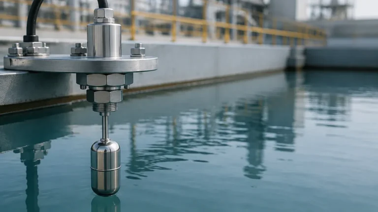
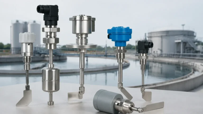
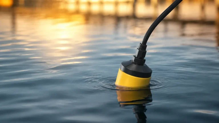
* Float Switches: Use a buoyant object that moves with the liquid level to open or close a mechanical switch.
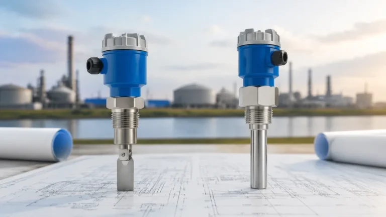
* Tuning Fork Switches: Vibrate at a specific frequency; when covered by the medium, the frequency changes, triggering the output.
* Capacitance Switches: Detect changes in electrical capacitance between the probe and the tank wall.
Standardized Symbology: ISA-5.1 and P&ID Conventions
The most common level sensor symbol is a circle (often called a bubble). The lines drawn through or around this circle indicate the mounting location:
* No Line: Field-mounted instrument (located at the tank or pipe).
* Solid Horizontal Line: Located in a primary control room, accessible to the operator.
* Double Solid Horizontal Line: Located in a secondary or local control panel.
* Dashed Horizontal Line: Located behind a panel or in a restricted area (not normally accessible).
Common Letter Combinations
| Letter Code | Meaning | Typical Application |
| :— | :— | :— |
| LT | Level Transmitter | Continuous level monitoring (e.g., 0-10 meters). |
| LI | Level Indicator | A local gauge or digital display showing the level. |
| LSH | Level Switch High | Triggers an alarm or stops a pump at a high setpoint. |
| LSL | Level Switch Low | Triggers an alarm or starts a pump at a low setpoint. |
| LSHH | Level Switch High-High | Emergency shutdown point to prevent catastrophic overflow. |
| LIC | Level Indicator Controller | A device that both displays the level and controls a valve/pump. |
Detailed Breakdown of Level Sensor Symbols for Different Technologies
While the "bubble" provides the functional identification, specific graphic symbols are often used to represent the physical sensing element on a P&ID.
1. The Float Symbol: Usually depicted as a small circle or ball connected by a line to the switch mechanism. This is the standard level sensor symbol for mechanical float-operated devices.
2. The Radar/Ultrasonic Symbol: Often shown as a small horn or a wave-emitting icon at the top of the tank vessel.
3. The Differential Pressure (DP) Symbol: Represented by two lines connecting to the tank (one at the bottom, one at the top/vapor space) leading to a transmitter body, used for pressurized vessels.
4. The Magnetic Level Gauge: Depicted as a vertical column on the side of the tank, often with an "LG" (Level Gauge) designation.
In complex automation, these symbols are integrated into a "loop." A typical loop might show an LT (Transmitter) sending a signal to an LIC (Controller), which then sends a command to an LV (Level Valve) to maintain a setpoint.

Selection Criteria for Level Measurement Technologies
Choosing the right instrument—and therefore the correct level sensor symbol for your documentation—requires an evaluation of the process environment.
| Feature | Radar Level Meter | Ultrasonic Sensor | Level Switch (Tuning Fork) | Hydrostatic Transmitter |
| :— | :— | :— | :— | :— |
| Measurement Type | Continuous | Continuous | Point | Continuous |
| Contact Type | Non-contact | Non-contact | Contact | Contact |
| Accuracy | High (±2mm) | Moderate (±0.25%) | N/A (Point detection) | Moderate (±0.1% to 0.5%) |
| Pressure Range | Up to 160 bar | Typically < 3 bar | Up to 64 bar | Up to 40 bar |
| Media Constraints | None (mostly) | Foam/Vapor issues | Viscosity limits | Density must be constant |
| Cost | High | Low to Medium | Low | Medium |
When the application requires simple overflow protection or dry-run protection for pumps, Level Switches are the most cost-effective and reliable choice. For inventory management in large silos or chemical tanks, a continuous radar transmitter is preferred.
Installation Guidelines and Symbol Interpretation
The way a level sensor symbol is placed on a P&ID dictates how the physical installation should occur.
1. Nozzle Positioning
For top-mounted sensors like radar or ultrasonic, the symbol is usually centered or slightly offset on the tank top. In practice, these must be installed away from the tank wall (to avoid false reflections) and away from the fill inlet (to avoid interference from falling material).
2. Dead Zones (Blocking Distance)
Every continuous level sensor has a "dead zone" or blocking distance—an area directly beneath the sensor where it cannot measure. For an ultrasonic sensor, this might be 0.2m to 0.5m. This must be accounted for in the vessel design to ensure the LSHH (High-High) point is not within this zone.
3. Stillwells and Bypass Chambers
In tanks with heavy agitation or turbulence, the P&ID may show a level sensor symbol inside a vertical pipe. This is a stillwell or bypass chamber. It provides a calm surface for the sensor to measure, ensuring a stable signal.
4. Venting
For hydrostatic sensors in closed tanks, the transmitter must be referenced to the tank's internal pressure, not atmospheric pressure. This is represented by a dual-connection symbol on the P&ID.
Limitations and Common Pitfalls in Symbol Application
While standardized, the use of level sensor symbols can lead to errors if not handled with care:
* Ambiguity in Technology: A circle labeled "LT" does not tell the technician if the device is radar, ultrasonic, or hydrostatic. Supplemental notes or a separate Instrument Index must be used to clarify the technology.
* Density Variations: Hydrostatic level symbols assume a constant liquid density. If the process involves fluids with changing densities (e.g., mixing different chemicals), the "LT" symbol might provide inaccurate data unless compensated by a PLC.
* Scale Misinterpretation: On a P&ID, the vertical position of a level switch symbol (LSH vs. LSL) is relative. The actual physical height (e.g., 2500mm from the tank floor) must be specified in the data sheet to ensure correct installation.
* Power and Signal Wiring: The symbol does not usually show whether the device is 2-wire (loop-powered) or 4-wire. This detail is reserved for the electrical loop diagrams.
Frequently Asked Questions (FAQ)
Q: What is the difference between a Level Transmitter (LT) and a Level Switch (LS) on a diagram?
A: An LT provides a continuous signal representing the exact level (e.g., 45% full), whereas an LS provides a binary signal (on/off) indicating that the liquid has reached a specific height.
Q: How is a redundant level system symbolized?
A: Redundancy is often shown by two identical symbols (e.g., two LTs) placed side-by-side on the vessel, often labeled with suffixes like LT-101A and LT-101B.
Q: Does a level sensor symbol change for solids vs. liquids?
A: Generally, the ISA-5.1 letter codes remain the same ("L" for Level). However, the graphic symbol for the sensing element might change—for example, a rotating paddle symbol is often used for bulk solids point level detection.
Q: What does a circle with a square around it mean?
A: In many modern P&IDs, a square around the circle indicates a function implemented in a Distributed Control System (DCS) or a Programmable Logic Controller (PLC) rather than a discrete physical instrument.
Q: Why are there multiple level switches on one tank?
A: Multiple Level Switches are used to provide different layers of protection. For example, an LSL might start a refill pump, an LSH might stop it, and an LSHH might trigger an emergency alarm to prevent a spill.
By adhering to these symbolic standards and understanding the physical principles of the hardware, engineers can ensure that their designs are translated accurately from the drawing board to the plant floor. For those seeking reliable components to fulfill these designs, Welk provides a comprehensive range of industrial level measurement solutions tailored to various process requirements.