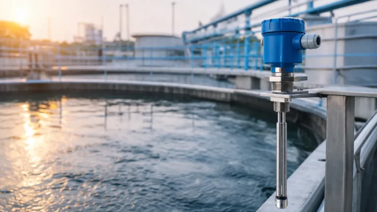
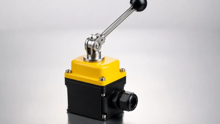
Radar Level Switches
Radar Level Switches
In the landscape of industrial automation, point-level detection serves as a critical safety and process control mechanism. Among the various technologies available, radar level switches have emerged as a high-precision, non-contact solution for demanding environments where traditional mechanical or ultrasonic sensors may fail. These devices utilize electromagnetic waves to detect the presence or absence of a medium at a specific height, providing reliable switching signals for overfill protection, dry-run prevention, and pump control.
While continuous radar level meters provide a constant data stream of the vessel's contents, radar level switches are optimized for discrete state changes. This article examines the engineering principles, selection criteria, and installation best practices for integrating these instruments into industrial workflows.
Understanding Radar Level Switches and Their Measurement Principles
Radar level switches operate on the principle of Time of Flight (ToF) or Frequency Modulated Continuous Wave (FMCW) technology, though the internal logic is simplified to provide a binary output (on/off). The device emits high-frequency electromagnetic pulses—typically in the microwave spectrum (6 GHz to 80 GHz)—toward the material surface.
The Physics of Reflection
When the emitted microwave hits a medium, a portion of the energy is reflected back to the sensor. The strength of this reflection depends heavily on the dielectric constant ($ε_r$) of the material. Materials with high dielectric constants, such as water (ε_r ≈ 80), reflect signals strongly, while hydrocarbons or dry solids (ε_r < 3) reflect much weaker signals.
Signal Processing for Point Detection
Unlike continuous transmitters that calculate the exact distance to the product, a radar level switch is configured with a specific "switching window." When the reflected signal's amplitude and time-of-flight match the parameters defined for the target level, the internal electronics trigger a relay or transistor output. Modern Level Switches utilize advanced signal processing algorithms to filter out "noise" caused by agitators, internal tank structures, or heavy vapor, ensuring that the switch only activates when the actual product reaches the sensor's focal point.
Key Advantages of Radar Technology in Point Level Detection
Radar level switches offer several distinct advantages over traditional technologies like vibrating forks, floats, or ultrasonic sensors:
1. Non-Contact Measurement: Because the sensor does not touch the medium, it is immune to corrosion, coating, and mechanical wear. This is particularly beneficial in hygienic food applications or highly corrosive chemical processing.
2. Immunity to Process Conditions: Radar waves are electromagnetic, meaning they do not require a medium for propagation. Consequently, they are unaffected by vacuum, high pressure, extreme temperatures, or changes in gas composition within the vessel.
3. Performance in Dust and Steam: Unlike ultrasonic sensors, which can be attenuated by heavy dust or steam, radar signals penetrate these atmospheric interferences with minimal loss of accuracy.
4. High Frequency Precision: Modern 80 GHz radar level switches feature a very narrow beam angle (often less than 6°), allowing them to be installed in narrow nozzles or vessels with internal obstructions without interference.
Technical Comparison: Radar vs. Traditional Level Switches
Selecting the correct technology requires understanding how radar compares to other common point-level instruments. The following table provides a comparison based on typical process requirements.
| Feature | Radar Level Switches | Vibrating Fork Switches | Ultrasonic Switches | Capacitance Switches |
| :— | :— | :— | :— | :— |
| Measurement Type | Non-contact | Contact | Non-contact | Contact |
| Media Type | Liquids & Solids | Liquids & Granular Solids | Primarily Liquids | Liquids & Solids |
| Effect of Build-up | Minimal | Moderate | High | High |
| Pressure Range | Up to 160 bar (16 MPa) | Up to 64 bar (6.4 MPa) | Typically < 3 bar | Up to 100 bar |
| Temp. Range | -40°C to +250°C+ | -50°C to +150°C | -40°C to +80°C | -50°C to +200°C |
| Dielectric Sensitivity| High | None | None | Very High |
Selection Criteria for Radar Level Switches
When specifying a radar level switch for a project, engineers must evaluate several environmental and material factors to ensure long-term reliability.
Dielectric Constant (ε_r)
This is the most critical factor. If the medium has a very low dielectric constant (e.g., liquefied gases or certain plastic pellets), the reflected signal may be too weak for a standard radar switch. In these cases, a high-sensitivity version or a guided wave radar (GWR) variant may be required.
Vessel Geometry and Internal Obstructions
The beam angle of the switch determines how close it can be mounted to a wall or an agitator. A wider beam angle (common in lower frequency 6 GHz or 26 GHz units) requires a larger clearance. For small tanks or tanks with cooling coils, an 80 GHz unit with a narrow beam is preferred.
Process Temperature and Pressure
Standard radar switches are often rated for temperatures up to 80°C or 150°C. For high-temperature applications, such as molten salts or steam boilers, specialized glass-to-metal seals and cooling fins are necessary to protect the sensor electronics.
Output Requirements
Engineers must decide between different output types:
* Relay (SPDT): For direct control of pumps or valves.
* Transistor (PNP/NPN): For integration into a PLC or DCS.
* Two-wire (8/16mA): For loop-powered systems where the current level indicates the switch state.
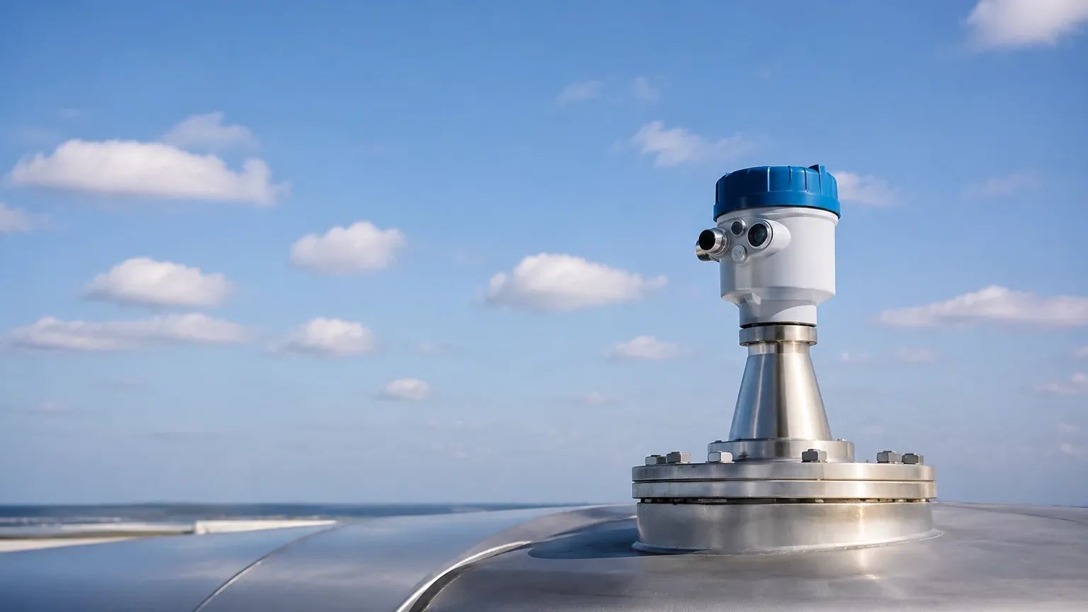
Installation Guidelines for Optimal Performance
Proper installation is essential to prevent false triggering and ensure the radar level switch performs to its technical specifications.
1. Nozzle Height and Diameter: The sensor antenna should ideally extend slightly beyond the mounting nozzle to prevent "ringing" or internal reflections within the nozzle. If the nozzle is long, a higher frequency radar (80 GHz) is recommended to minimize signal interference.
2. Orientation: The switch should be mounted vertically, perpendicular to the product surface. For solids, where the material forms a cone, the switch may need to be aimed toward the slope to ensure a consistent reflection.
3. Avoid the Fill Stream: Never install a radar level switch directly under the filling inlet. The turbulence and the falling stream of material will cause erratic readings and potential false alarms.
4. Dead Zones: Every radar sensor has a "dead zone" (blocking distance) near the antenna where measurement is not possible. Ensure the switch is mounted high enough that the maximum product level does not enter this zone, typically between 50 mm and 200 mm depending on the model.
Limitations and Practical Considerations
While radar is highly versatile, it is not a universal solution for every application. Engineers should be aware of the following limitations:
* Heavy Foaming: Extremely dense, thick foam can absorb radar signals rather than reflecting them. If the application involves consistent heavy foam, a contact-based technology like a vibrating fork may be more reliable.
* Extremely Low Dielectric Media: Materials with a dielectric constant below 1.5 may not reflect enough energy for a non-contact radar switch to detect.
* Cost: Radar technology generally carries a higher initial investment compared to simple float switches or conductive probes. However, the total cost of ownership (TCO) is often lower due to reduced maintenance and longer service life.
Frequently Asked Questions (FAQs)
Q: Can radar level switches detect the interface between two liquids?
A: Standard point-level radar switches are typically designed to detect the top surface. For interface detection (e.g., oil on top of water), guided wave radar (GWR) or specialized continuous radar sensors are usually required.
Q: Do I need to recalibrate the switch if the medium changes?
A: If the new medium has a significantly different dielectric constant, the sensitivity threshold may need adjustment. However, for most liquids with ε_r > 10, the switch will function reliably without recalibration.
Q: Is it possible to use a radar level switch in a plastic tank?
A: Yes. Radar waves can penetrate plastic and fiberglass. It is possible to mount the sensor outside a plastic tank to measure the level through the wall, provided the wall thickness is not excessive and the medium has a high dielectric constant.
Q: How does turbulence affect the switch?
A: Radar level switches are generally more resistant to turbulence than ultrasonic sensors. Modern units use integration time delays (damping) to ensure that momentary splashes do not trigger a false alarm.
Conclusion
Radar level switches represent the pinnacle of point-level detection technology for modern industrial processes. By offering a non-contact, maintenance-free alternative to traditional sensors, they provide high reliability in environments characterized by extreme temperatures, pressures, and corrosive chemicals. When selecting a switch, focusing on the dielectric properties of the media and the specific geometry of the vessel will ensure an optimized installation that enhances both process safety and operational efficiency.