Water Level Switches
Water Level Switches
In industrial automation and fluid management, the ability to detect the presence or absence of liquid at a specific point is fundamental to process safety and efficiency. Water level switches serve as the primary line of defense against tank overflows, pump dry-running, and unauthorized drainage. Unlike continuous level transmitters that provide a constant data stream of the liquid's height, a level switch acts as a binary sensor, triggering an electrical signal when the water reaches a predetermined threshold.
Selecting the appropriate technology for water level detection requires an understanding of the physical properties of the water being measured—whether it is ultrapure deionized water, municipal wastewater, or high-temperature condensate—and the mechanical constraints of the installation environment. This guide examines the measurement principles, selection criteria, and installation best practices for industrial Level Switches used in water-based applications.
Measurement Principles of Water Level Switches
Before selecting a device, engineers must understand how different sensing technologies interact with water. The choice of principle often depends on the water's conductivity, viscosity, and the presence of contaminants.
Mechanical Float Principle
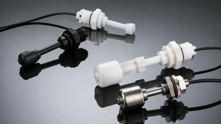
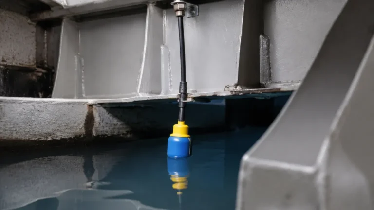
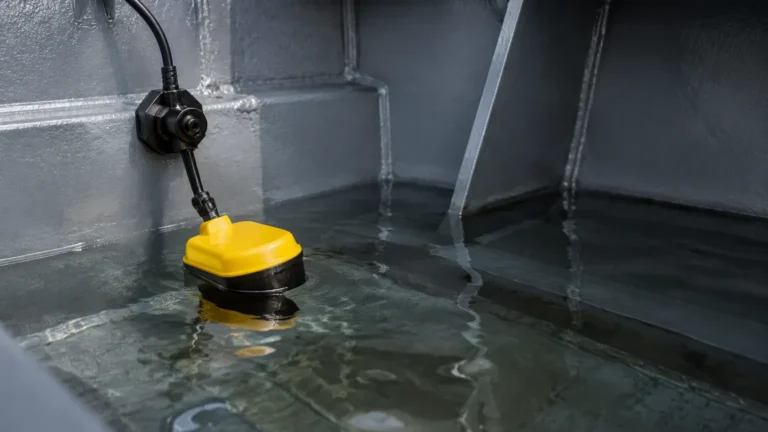
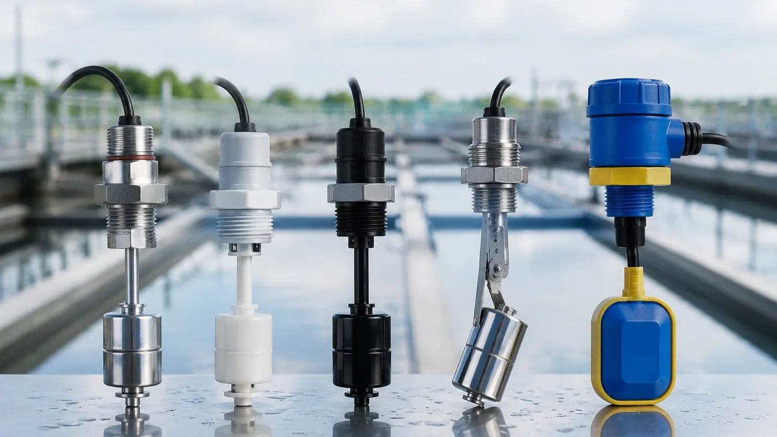
The most traditional method relies on buoyancy. A float, typically made of stainless steel or plastic, contains a permanent magnet. As the water level rises, the float moves along a stem or pivots on a hinge. When the magnet reaches a specific position, it actuates a reed switch or a microswitch. This technology is purely mechanical in its sensing stage and does not require power to detect the level, making it highly reliable for simple high/low alarms.
Vibrating Tuning Fork Principle
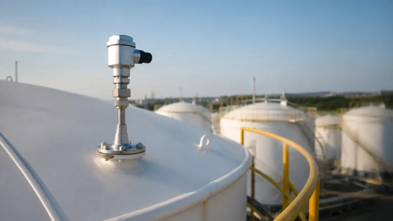
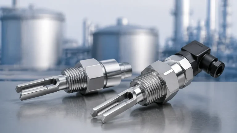
Electronic vibrating switches use a piezoelectric crystal to vibrate a metal fork at its natural resonant frequency in the air. When the fork is immersed in water, the frequency changes due to the increased density of the medium. An internal circuit detects this frequency shift and switches the output state. This method is highly resistant to turbulence, foam, and bubbles, which often cause false trips in other sensors.
Conductive Principle
Conductive water level switches utilize the electrical conductivity of water. Two or more electrodes are placed in the tank. When the water level rises and touches the electrodes, an electrical circuit is completed through the liquid. This low-voltage current is then used to trigger a relay. This is a cost-effective solution for conductive liquids but is unsuitable for oil, pure deionized water, or applications where electrolysis might occur.
Capacitive Principle
Capacitive sensors treat the probe and the tank wall (or a reference electrode) as two plates of a capacitor. Water has a high dielectric constant (approximately 80) compared to air (1). As water fills the space between the probe and the wall, the capacitance increases. The electronics convert this change into a switching signal. These are effective for detecting water through non-metallic tank walls or in applications with coating-prone liquids.
Ultrasonic Point Level
Ultrasonic switches use a pair of crystals (transmitter and receiver) separated by a small gap. When the gap is filled with air, the ultrasonic signal cannot bridge the space efficiently. When water enters the gap, the signal passes through, signaling the presence of liquid. This is a non-contact sensing method within the gap itself, reducing wear and tear.
Comparison of Technologies for Water Level Detection
Choosing the right water level switches involves balancing cost, maintenance requirements, and application compatibility. The following table provides a comparative overview of common technologies.
| Technology | Best Application | Advantages | Limitations |
| :— | :— | :— | :— |
| Float Switch | Clean water tanks, sumps | Low cost, no power needed for sensing | Moving parts can jam; prone to scaling |
| Vibrating Fork | Industrial process water, cooling loops | High reliability, ignores foam/bubbles | Higher initial cost; sensitive to heavy buildup |
| Conductive | Wastewater, boiler feed water | Very simple, multiple setpoints | Requires conductive liquid; probe fouling |
| Capacitive | Chemical-treated water, plastic tanks | No moving parts, adjustable sensitivity | Affected by changes in water composition |
| Ultrasonic Gap | High-purity water, oils | Non-mechanical, long service life | Higher cost; sensitive to heavy aeration |
Selection Criteria for Industrial Applications
When specifying a switch for water level management, several technical parameters must be confirmed to ensure long-term performance.
1. Water Quality and Composition
Not all water is the same. In wastewater treatment, the presence of solids or fibrous materials can entangle mechanical float switches. In these cases, non-contact or vibrating fork sensors are preferred. Conversely, for potable water, materials must be food-grade (e.g., 316 stainless steel or specific plastics like PP or PVDF) to prevent contamination.
2. Temperature and Pressure
Standard plastic float switches are often limited to 80°C (176°F) and low pressures. For boiler applications or high-temperature condensate return systems, stainless steel switches rated for 150°C (302°F) and pressures exceeding 20 bar (290 psi) are necessary. Always verify the maximum operating limits of the housing and the sensing element.
3. Tank Geometry and Mounting
Determine if the switch will be mounted from the top (vertical) or the side (horizontal). Vertical mounting is ideal for deep sumps where the switch can be suspended by a cable. Side mounting is common for high/low alarms in process tanks where top access is restricted. Ensure that the "dead zone" or the distance required for the switch to reset is factored into the tank's operational volume.
4. Output Requirements
Most industrial level switches offer a Relay (SPDT/DPDT) or a Transistor (PNP/NPN) output. For integration into a PLC (Programmable Logic Controller), a transistor output provides faster switching and longer life, while a relay output is better suited for directly controlling small pumps or solenoids.
Installation Considerations and Best Practices
Proper installation is as critical as selecting the right technology. Failure to account for the physical dynamics of the tank can lead to premature failure or inaccurate readings.
* Avoid Turbulence: Do not install water level switches directly in the path of an inlet pipe or near a high-speed agitator. The constant motion can cause "chatter" (rapid cycling of the switch) or mechanical fatigue. If placement near an inlet is unavoidable, use a stilling well—a perforated pipe that surrounds the sensor to dampen wave action.
* Orientation Matters: For float switches, ensure the stem is perfectly vertical (within ±5 degrees) to prevent the float from sticking. For side-mounted vibrating forks, the tines should be oriented so that liquid can drain off them easily, preventing false "wet" signals due to liquid retention.
* Cable Management: In outdoor or wash-down environments, always use a drip loop in the cabling. This prevents water from running down the wire and entering the sensor housing through the cable gland. Ensure the IP rating (e.g., IP65, IP67, or IP68) matches the exposure level.
* Grounding: For conductive and capacitive switches, proper grounding of the tank (if metal) or the use of a ground electrode is essential for a stable signal. Without a common ground, the sensor may experience electrical noise and erratic behavior.
Limitations and Common Risks
While water level switches are robust, they are not immune to environmental challenges. Understanding these risks helps in developing a maintenance schedule.
1. Scaling and Buildup: In hard water applications, calcium and magnesium deposits can accumulate on the sensor. This is particularly problematic for mechanical floats, which may become stuck, and conductive probes, which may lose electrical contact. Regular inspection and cleaning with a mild descaling agent are recommended.
2. Coating: In wastewater or water containing oils/fats, a film can develop over the sensor. Vibrating forks and capacitive switches with "active shield" technology are better at ignoring coating, but excessive buildup will eventually dampen the vibration or shift the capacitance beyond the trigger point.
3. Electromagnetic Interference (EMI): Electronic switches installed near high-power motors or variable frequency drives (VFDs) can suffer from signal interference. Using shielded cables and ensuring the sensor housing is properly bonded to the system ground can mitigate this risk.
Frequently Asked Questions (FAQs)
Q: Can a water level switch be used for continuous monitoring?
No. A level switch only identifies if the water is above or below a specific point. For continuous tracking (e.g., 0% to 100% full), you require a level transmitter, such as an ultrasonic or radar level meter.
Q: How do I test if my level switch is functioning correctly?
Most electronic switches include a local LED indicator. For mechanical switches, a multimeter can be used to check continuity across the contacts while manually moving the float. In a live system, many engineers perform a "wet test" by intentionally raising the water level during commissioning.
Q: What is the difference between "Normally Open" (NO) and "Normally Closed" (NC)?
This refers to the state of the electrical switch when the water is not present. A "Normally Open" switch closes the circuit when water reaches it (often used for high-level alarms), while a "Normally Closed" switch opens the circuit when water reaches it (often used for low-level pump protection).
Q: Are there switches suitable for seawater or brine?
Yes, but material selection is vital. Standard 304 stainless steel will corrode in salt water. For these applications, use 316L stainless steel, titanium, or plastic materials like PVC or PP to ensure longevity.
Conclusion
Water level switches are essential components in the architecture of modern industrial fluid systems. By selecting a technology that aligns with the specific characteristics of the water—be it through buoyancy, vibration, or conductivity—engineers can ensure reliable automated control and protection. Whether preventing a flood in a municipal pumping station or protecting a high-pressure boiler from dry-firing, the correct switch provides the necessary peace of mind for safe operations.
For those evaluating specific hardware for a new project or replacement, it is advisable to consult technical datasheets to confirm chemical compatibility and electrical ratings before installation.