Optical Liquid Level Switches
Optical Liquid Level Switches
In the landscape of industrial automation, point-level detection serves as a critical safeguard for equipment protection, overflow prevention, and process control. Among the various technologies available, optical liquid level switches have emerged as a preferred solution for applications requiring high reliability, compact footprints, and no moving parts. This guide explores the engineering principles, selection criteria, and practical installation considerations for optical level sensing technology.
Understanding the Measurement Principle
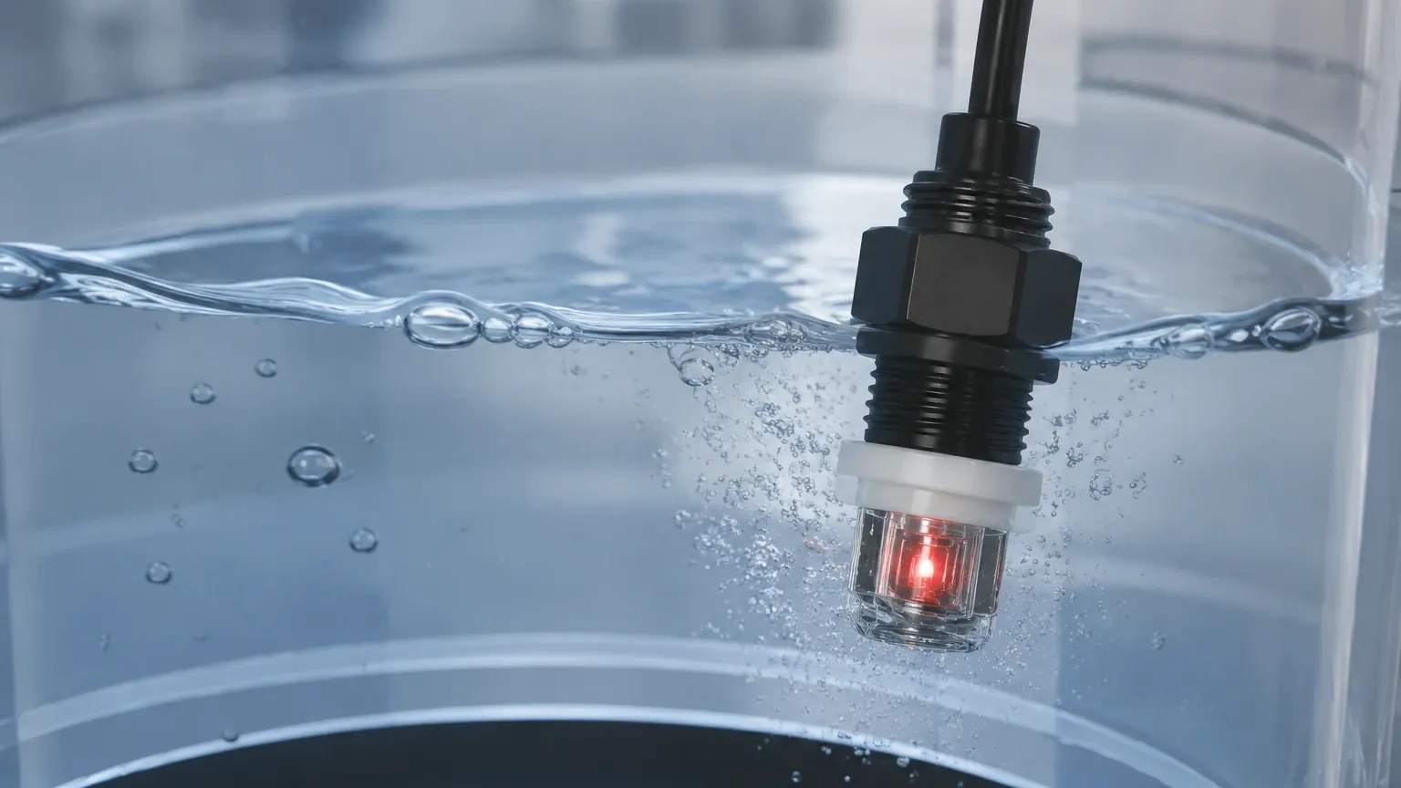
Optical liquid level switches operate based on the principles of infrared light reflection and refraction. Unlike float switches that rely on mechanical movement or ultrasonic sensors that use sound waves, optical sensors utilize a solid-state approach that minimizes wear and tear.
The Optical Prism Mechanism
The core of an optical level switch consists of an internal Infrared (IR) LED and a phototransistor, housed behind a plastic or glass cone (the prism). The sensing process follows two distinct states:
1. Dry State (Air): When the sensor tip is in the air, the infrared light emitted by the LED is internally reflected within the prism and directed back to the phototransistor. This completes the optical circuit, signaling that the liquid level is below the sensor point.
2. Wet State (Liquid): When the sensor tip is submerged in a liquid, the refractive index at the interface changes. The infrared light, rather than reflecting back, refracts out into the liquid. Consequently, the phototransistor receives significantly less or no light, triggering a change in the output signal to indicate the presence of the liquid.
Because this technology relies on the optical properties of the medium rather than its density, conductivity, or dielectric constant, it is highly effective for a wide range of clean liquids.
Key Components and Design Variations
To meet the diverse requirements of industrial environments, optical level switches are manufactured in several configurations. Choosing the right design is essential for long-term performance.
Housing Materials
The choice of housing material determines the sensor's chemical compatibility and pressure resistance. Common materials include:
* Polysulfone (PSU): A standard high-performance thermoplastic suitable for most water-based liquids and many chemicals. It offers good transparency for the IR signal and is cost-effective.
* Trogamid (PA): Often used for applications involving fuels, oils, and hydrocarbons where PSU might degrade.
* Stainless Steel with Glass/Quartz Tip: For high-pressure environments (up to 50 bar or 5 MPa) and aggressive chemical processes. The robust metal body provides mechanical strength, while the glass tip ensures optical clarity.
Output Configurations
Most industrial Level Switches utilize solid-state outputs to interface with Programmable Logic Controllers (PLCs) or alarm systems. Common types include:
* NPN/PNP Open Collector: Standard for DC circuits (typically 5V to 24V DC), allowing for easy integration into digital input cards.
* High/Low Logic: Sensors can be configured as "Normally Open" (output high when dry) or "Normally Closed" (output high when wet) depending on the fail-safe requirements of the application.
Application Suitability and Industry Use Cases
Optical liquid level switches are particularly valued in industries where space is limited and high precision is required. Their lack of moving parts makes them ideal for high-vibration environments or applications where mechanical floats might jam due to debris or coating.
Medical and Laboratory Equipment
In clinical analyzers and laboratory automation, precision is paramount. Optical sensors are used to monitor reagent levels and waste containers. Their small form factor (often with M12 or smaller threads) allows them to be integrated into compact manifolds.
Food and Beverage
Stainless steel variants are frequently used in the food industry for detecting levels in bottling lines and storage tanks. Because the sensing tip is smooth and non-porous, it meets the hygiene requirements necessary to prevent bacterial growth.
Industrial Hydraulics and HVAC
Monitoring oil levels in hydraulic reservoirs or condensate levels in HVAC systems are classic use cases. The ability of optical liquid level switches to operate reliably in oils and refrigerants without being affected by the fluid's dielectric properties gives them an advantage over capacitive sensors.
Selection Criteria for Optical Liquid Level Switches
When specifying an optical sensor for a project, engineers must evaluate several environmental and fluid-specific factors to ensure accurate switching.
1. Liquid Characteristics
While optical switches work well with most liquids, the following properties must be considered:
* Transparency: The liquid must be capable of absorbing or refracting the IR light. Extremely reflective or opaque liquids may occasionally require sensitivity adjustments.
* Viscosity: Highly viscous liquids can leave a thick film on the prism tip when the level drops, potentially causing a "false wet" reading. In these cases, a conical tip design that encourages drainage is preferred.
* Aeration and Bubbles: Large bubbles clinging to the sensor tip can mimic a dry state. Proper placement away from inlets or agitators is necessary.
2. Environmental Conditions
* Ambient Light: Intense direct sunlight or high-frequency fluorescent lighting can interfere with the IR receiver. Sensors with modulated light or shielded housings are recommended for outdoor use.
* Temperature and Pressure: Standard plastic sensors typically handle up to 85°C and 7 bar (0.7 MPa). For steam cleaning or high-pressure vessels, stainless steel models rated for 125°C and 50 bar are required.
3. Mounting Orientation
Optical switches can be mounted horizontally (side-wall), vertically (top-down), or even at an angle. However, vertical mounting from the top is often preferred to allow liquid to drip off the tip naturally, reducing the risk of false triggers from residual droplets.
Technical Comparison Table
The following table provides a general reference for comparing different optical switch configurations based on typical Welk industrial standards.
| Feature | Plastic (PSU/Trogamid) | Stainless Steel / Glass | High-Pressure Series |
| :— | :— | :— | :— |
| Max Pressure | 7 bar (0.7 MPa) | 25 bar (2.5 MPa) | 50 bar (5.0 MPa) |
| Temp Range | -20°C to +85°C | -30°C to +100°C | -40°C to +125°C |
| Chemical Resistance | Moderate (Water/Oils) | High (Acids/Solvents) | Excellent |
| Typical Thread | M12 x 1 | G 1/2" or NPT 1/2" | G 1/2" or Flanged |
| Output Type | NPN/PNP | NPN/PNP/Relay | NPN/PNP/Relay |
Installation and Configuration Best Practices
Successful deployment of optical liquid level switches relies on adhering to specific engineering guidelines during the installation phase.
Positioning and Clearance
To avoid interference, the sensor tip should have a minimum clearance from any internal tank structures. If the sensor is mounted too close to a reflective wall (e.g., a polished stainless steel tank), the IR light might reflect off the wall and back into the sensor, causing it to remain in a "dry" state even when submerged. A minimum clearance of 20 mm to 50 mm is generally recommended depending on the sensor's sensitivity.
Wiring and Electrical Protection
* Shielding: In environments with high electromagnetic interference (EMI) from large motors or variable frequency drives (VFDs), use shielded cabling to prevent signal noise.
* Voltage Stability: Ensure the power supply is regulated. While most sensors accept a range (e.g., 10-28V DC), spikes can damage the internal LED or phototransistor.
* Reverse Polarity: Verify that the sensor includes reverse polarity protection to prevent damage during commissioning.
Dealing with Coating and Contamination
In applications where the liquid may contain particulates or cause scaling (such as hard water or wastewater), regular maintenance schedules should be established. A simple wipe-down of the prism tip with a soft cloth and a compatible solvent is usually sufficient to restore performance. If heavy coating is unavoidable, consider a sensor with a larger prism surface area or a different technology, such as a vibrating fork level switch.
Limitations and Maintenance Considerations
While optical liquid level switches are highly versatile, they are not universal solutions. Engineers should be aware of the following limitations:
* Heavy Foam: Thick, dense foam can sometimes be detected as a liquid, which may be desirable for foam control but problematic if only the liquid phase needs to be monitored.
* Coating and Crystallization: If a liquid dries and leaves a solid crust on the prism, the sensor will fail to detect the transition between wet and dry states.
* Small Tank Geometry: In very small pipes or narrow tubes, the curvature of the wall can cause internal reflections that interfere with the optical path.
Maintenance is minimal due to the lack of moving parts. Periodic visual inspections to ensure the prism is clear of debris and the electrical connections are secure are typically the only requirements for a service life that often exceeds ten years in standard conditions.
Frequently Asked Questions (FAQ)
Q: Can optical level switches detect the interface between two liquids (e.g., oil and water)?
A: Generally, no. Optical switches are designed to detect the presence or absence of a liquid by sensing the change from air to liquid. Since both oil and water will refract the light away from the sensor, the switch will trigger for both. Interface detection usually requires capacitive or specialized radar technology.
Q: How do I prevent false triggers from splashing?
A: False triggers can be mitigated by using a time-delay relay or PLC logic that requires the sensor to remain in a "wet" state for a specific duration (e.g., 2-3 seconds) before confirming a level change. Some advanced optical switches also feature built-in electronics to filter out momentary splashes.
Q: Are these sensors suitable for cryogenic applications?
A: Standard optical switches are not rated for cryogenic temperatures. Specialized low-temperature models with vacuum-sealed housings and specific materials are required for applications involving liquid nitrogen or LNG.
Q: Is it possible to use optical switches in hazardous (Ex) zones?
A: Yes, but you must select models that are specifically certified (e.g., ATEX or IECEx) and use them in conjunction with an intrinsically safe barrier to limit the energy available to the sensor in the hazardous area.
For engineers seeking a reliable, low-maintenance solution for point-level monitoring, optical liquid level switches offer an excellent balance of performance and cost. By understanding the optical properties of the process media and following standard installation practices, these sensors provide a robust layer of control for modern industrial systems.