.8 Gauges
.8 Gauges
In the field of industrial level measurement, the term ".8 gauges" typically refers to level indicators specifically engineered to operate with process media having a specific gravity (SG) of approximately 0.8. This density is a common benchmark in the petrochemical and chemical industries, as many hydrocarbons, oils, and solvents fall within this range. Ensuring that a level gauge is accurately calibrated for a 0.8 SG fluid is critical for safety, process efficiency, and inventory management.
Selecting the right instrumentation requires a deep understanding of how fluid density interacts with measurement hardware. For bypass-style indicators, such as Magnetic & Local Level Gauges, the specific gravity of the liquid dictates the design of the internal float, which is the heart of the measurement system. If the float is not precisely matched to the liquid density, the resulting reading will be inaccurate, or the gauge may fail to function entirely.
Measurement Principles of Magnetic Level Gauges
To understand why a 0.8 SG requirement is so specific, one must first understand the underlying physics of magnetic level measurement. These instruments operate based on two primary physical principles: Archimedes’ Principle of Buoyancy and the principle of magnetic coupling.
Archimedes’ Principle and Buoyancy
Archimedes' principle states that any object, wholly or partially immersed in a fluid, is buoyed up by a force equal to the weight of the fluid displaced by the object. In a magnetic level gauge, the float must be designed so that its weight is less than the weight of the liquid it displaces.
For a liquid with a specific gravity of 1.0 (water), a float has a relatively high amount of buoyant force to work with. However, as the specific gravity drops to 0.8, the fluid becomes less dense. This means the float must either be physically larger to displace more fluid or constructed from lighter materials to maintain the same level of buoyancy. If a float designed for water is placed in a 0.8 SG fluid, it will likely sink to the bottom of the chamber, resulting in a "low level" error regardless of the actual liquid height.
Magnetic Coupling
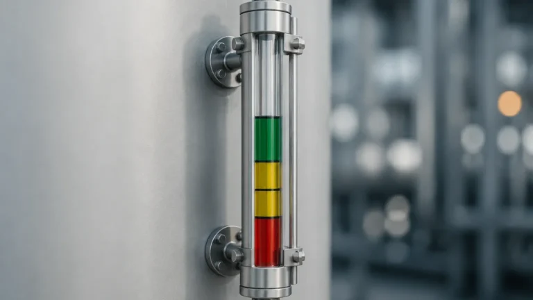
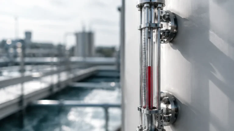
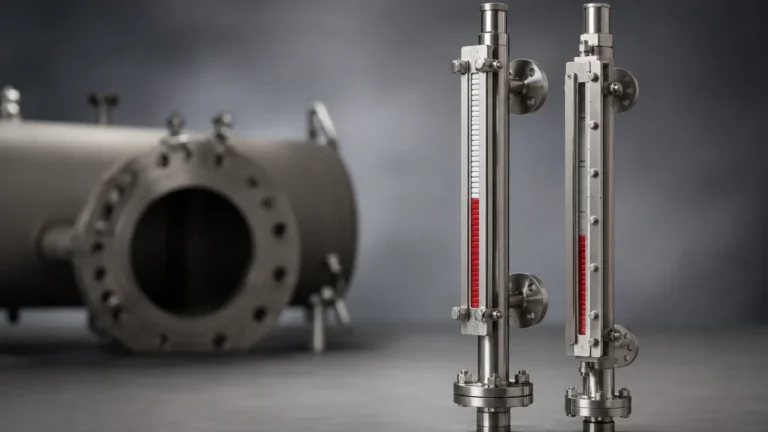
The float contains an internal ring of high-strength magnets. As the liquid level in the bypass chamber rises and falls, the float moves accordingly. Outside the chamber, a visual indicator—typically consisting of a series of bi-color magnetic flaps or a follower—is mounted. The magnetic field from the float penetrates the non-magnetic chamber wall (usually stainless steel) and flips the flags or moves the follower. This provides a clear, high-visibility local representation of the tank level without the need for glass windows that could leak or cloud over time.
The Significance of 0.8 Specific Gravity
A specific gravity of 0.8 is a transition point for many engineering specifications. Standard "off-the-shelf" floats are often weighted for water (1.0 SG) or slightly below. When dealing with .8 gauges, engineers must account for the decreased lifting force of the medium. Common fluids in this category include:
* Crude Oil and Refined Fuels: Many diesel fuels and light crudes range from 0.82 to 0.88 SG.
* Alcohols: Ethanol and methanol often hover around 0.79 to 0.81 SG.
* Aromatic Hydrocarbons: Benzene and toluene typically fall near the 0.86 to 0.87 range.
In these applications, Welk provides customized float designs where the center of the magnetic ring is precisely aligned with the liquid's surface at the specified 0.8 SG. This ensures that the "zero" point on the scale accurately reflects the top of the liquid column.
Selection Criteria for .8 Gauges
When specifying a magnetic level gauge for 0.8 SG applications, several technical factors must be evaluated to ensure long-term reliability and accuracy.
Float Material and Construction
For 0.8 SG fluids, the float must be lightweight yet capable of withstanding the process pressure.
1. Stainless Steel (316L): Common for moderate pressures. To achieve buoyancy in 0.8 SG, the wall thickness must be carefully balanced against the internal volume.
2. Titanium: Often the preferred choice for low-density fluids at high pressures. Titanium has a high strength-to-weight ratio, allowing for a float that is light enough to float in 0.8 SG media while resisting crushing at pressures exceeding 40 bar (580 PSI).
3. Plastic (PVC/PP/PVDF): Used for corrosive chemicals with 0.8 SG, provided the temperature and pressure remain low.
Chamber Diameter
Because floats for lower density liquids often need to be longer or wider to displace enough mass, the bypass chamber diameter may need to be increased. While a standard 2-inch (50 mm) schedule 40 pipe is common, 0.8 SG applications might require a 2.5-inch or 3-inch chamber to accommodate a high-buoyancy float.
Temperature and Pressure Effects
Fluid density is not static; it changes with temperature. A fluid that is 0.8 SG at 20°C (68°F) may drop to 0.75 SG at 100°C (212°F). The gauge must be designed for the *minimum* operating density to ensure the float never sinks during process upsets.
Technical Selection Table
The following table provides a general guideline for float selection in .8 gauges based on typical industrial parameters:
| Process Medium SG | Recommended Float Material | Max Pressure (Metric/Imperial) | Max Temperature | Chamber Size |
| :— | :— | :— | :— | :— |
| 0.80 – 0.90 | 316L Stainless Steel | 25 bar / 362 PSI | 250°C / 482°F | DN50 (2") |
| 0.75 – 0.85 | Titanium Grade 2 | 40 bar / 580 PSI | 400°C / 752°F | DN50 (2") |
| 0.80 – 1.00 | Hastelloy C276 | 20 bar / 290 PSI | 200°C / 392°F | DN65 (2.5") |
| 0.80 – 0.95 | PVDF / Plastic | 6 bar / 87 PSI | 100°C / 212°F | DN50 (2") |

Installation and Maintenance Considerations
Proper installation is paramount for the accuracy of .8 gauges. Because these instruments rely on mechanical buoyancy, any deviation from the design parameters can lead to measurement errors.
Vertical Alignment
The bypass chamber must be installed perfectly vertical. A tilt of even a few degrees can cause the float to rub against the chamber wall, creating friction that prevents it from following the liquid level accurately. This is particularly critical in 0.8 SG applications where the buoyant force is lower and less able to overcome mechanical resistance.
Magnetic Interference
Since the gauge relies on magnetic coupling, it must be kept away from large ferrous structures or strong electromagnetic fields (such as high-power motors or transformers). Standard practice suggests a minimum clearance of 100 mm (4 inches) from carbon steel supports.
Venting and Draining
Each gauge should be equipped with a vent valve at the top and a drain valve at the bottom. This allows for safe commissioning and periodic flushing. In 0.8 SG hydrocarbon service, paraffin or wax buildup can occur; regular flushing ensures the float remains free-moving.
Limitations and Application Risks
While magnetic level gauges are robust, they are not universal solutions. Engineers should be aware of the following limitations:
1. Viscosity: High-viscosity liquids (typically above 500 cP) can impede float movement. If the 0.8 SG liquid is a heavy oil that thickens at low temperatures, heat tracing may be required.
2. Coating and Scaling: If the process medium leaves deposits on the float, the float's weight will increase over time. In a 0.8 SG application, even a small amount of scale can cause the float to sit lower in the liquid, leading to a permanent negative offset in the reading.
3. Flashing and Boiling: If the liquid in the chamber flashes to vapor, the resulting turbulence can cause the float to bounce or become damaged. Internal dampeners or larger chambers are often necessary for boiling liquids.
4. Extreme Low Density: For fluids with an SG below 0.5 (such as LPG or LNG), magnetic level gauges require highly specialized, pressurized floats, often made of titanium, and larger chamber diameters.
Frequently Asked Questions (FAQ)
Q: Can I use a gauge designed for water (SG 1.0) on a 0.8 SG fluid?
A: Generally, no. The float will sit significantly deeper in the 0.8 SG liquid than it did in water, causing the indicator to show a level lower than the actual tank level. In many cases, a water float will sink entirely in a 0.8 SG medium.
Q: How do I verify the SG of my process?
A: SG should be verified at the operating temperature. You can use a hydrometer for manual samples or an online densitometer for continuous monitoring. Always provide the minimum, normal, and maximum SG to the gauge manufacturer.
Q: Is a magnetic level gauge better than a sight glass for 0.8 SG hydrocarbons?
A: Yes, in most industrial scenarios. Sight glasses are prone to leaking at the seals and can become dangerous if the glass breaks. Magnetic gauges offer a "sealless" design where the liquid is entirely contained within a metal pressure vessel, providing much higher safety for flammable 0.8 SG fluids.
Q: What maintenance is required for .8 gauges?
A: Maintenance is minimal. Periodically use the drain valve to remove sediment and check that the float moves freely. The external indicator requires no maintenance other than occasional cleaning for visibility.
For engineers and plant operators, selecting the correct Magnetic & Local Level Gauges involves more than just picking a height. By focusing on the specific gravity requirements—particularly the common 0.8 SG threshold—and ensuring float metallurgy and chamber design are aligned with process conditions, you can ensure a reliable and maintenance-free level measurement solution for years to come.