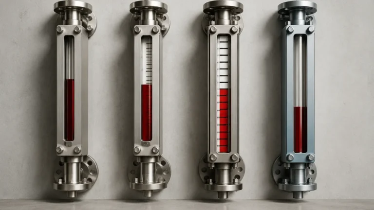
6 Gauges Set
6 Gauges Set
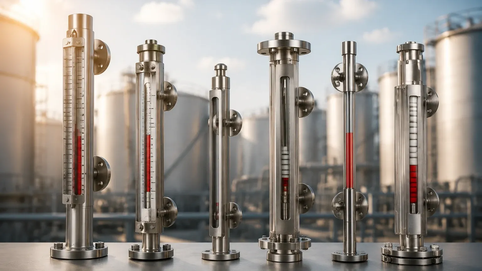
In industrial process control, the requirement for a "6 gauges set" often arises during the commissioning of modular skid systems, multi-tank storage facilities, or high-rise distillation columns. When managing a project that involves multiple measurement points, standardizing on a specific set of Magnetic & Local Level Gauges ensures consistency in maintenance, spare parts inventory, and operator training. This guide examines the technical specifications, selection criteria, and installation best practices for implementing a set of six level gauges within a professional industrial environment.
Understanding the Principles of Magnetic and Local Level Gauges
Before selecting a 6 gauges set, it is essential to understand the underlying physics that allow these instruments to provide reliable, power-free level indication. Magnetic level gauges operate on two primary physical principles: buoyancy and magnetic coupling.
The Buoyancy Principle
The gauge consists of a bypass chamber connected to the side of a vessel. According to Archimedes' principle, the liquid level inside the chamber rises and falls in equilibrium with the level inside the main vessel. Inside this chamber is a float, specifically engineered to match the density of the process fluid. As the liquid level shifts, the float moves vertically within the chamber.
Magnetic Coupling
The float contains a high-intensity internal magnet assembly. Outside the chamber, a visual indicator (often consisting of bi-color magnetic flaps or a follower) is mounted. Because the chamber is non-magnetic—typically constructed from 316 stainless steel or specialized plastics—the magnetic field from the float passes through the chamber wall. This field acts upon the external indicator, flipping the flags from one color to another (e.g., white to red) to provide a clear, high-visibility representation of the liquid level without the need for glass windows or direct contact with the process fluid.
Applications for a 6 Gauges Set
Procuring a 6 gauges set is a common strategy for engineering firms and plant managers who need to equip a specific process area. Common scenarios include:
1. Tank Batteries: In water treatment or chemical storage, fluids are often distributed across a battery of six identical tanks. Using a standardized set ensures that every tank has the same visual reference scale and maintenance requirements.
2. Fractionation Columns: For very tall vessels where a single gauge would be mechanically impractical or difficult to transport, a set of gauges can be staggered to cover the entire height of the column.
3. Redundant Monitoring: In critical oil and gas applications, multiple gauges may be installed on a single high-pressure vessel to provide redundancy and verify the accuracy of electronic transmitters.
4. OEM Skid Manufacturing: Manufacturers of chemical dosing skids or fuel filtration systems often require a 6 gauges set to complete a production run of standardized equipment modules.
Key Selection Criteria for Industrial Level Gauges
Selecting the right instruments for your 6 gauges set requires a deep dive into the process conditions. The following factors are authoritative boundaries for any engineering specification:
Fluid Density (Specific Gravity)
The float must be lighter than the liquid it displaces. If the specific gravity (SG) of the fluid changes due to temperature fluctuations or chemical concentration, the float may sink or ride too high, leading to inaccuracies. Standard floats are typically designed for an SG range of 0.5 to 2.0.
Pressure and Temperature Ratings
Because the bypass chamber is an extension of the pressure vessel, it must meet the same design codes (such as ASME B31.3). A 6 gauges set used in high-pressure steam applications will require significantly different wall thicknesses and flange ratings than a set used for ambient-pressure water storage.
Material Compatibility
The wetted parts—the chamber and the float—must be chemically compatible with the process medium. While 316L stainless steel is the industry standard, highly corrosive environments may require exotic alloys like Hastelloy, Monel, or plastic linings like PTFE (Polytetrafluoroethylene).
Practical Selection Table for Level Gauges
When evaluating options for a 6 gauges set, use the following table to align your project requirements with standard industrial specifications.
| Feature | Standard Industrial | High Pressure/Temp | Corrosive/Chemical |
| :— | :— | :— | :— |
| Chamber Material | 304/316 Stainless Steel | Heavy-wall 316 Ti | PVC, PP, or PVDF |
| Max Pressure | 40 bar (580 psi) | Up to 250 bar (3625 psi) | 6 bar (87 psi) |
| Temperature Range | -20°C to 150°C | -196°C to 450°C | 0°C to 80°C |
| Connection Type | Flanged (DN20/25) | RTJ Flange / Weld Neck | Threaded or Solvent Weld |
| Indicator Type | Aluminum Flaps | Ceramic Flaps | Plastic Flaps |
| Accuracy | ±10 mm | ±10 mm | ±10 mm |
Installation and Maintenance Considerations
Proper installation is critical to the longevity of a 6 gauges set. Even the most robust Magnetic & Local Level Gauges will fail if the physical installation is compromised.
Alignment and Verticality
The bypass chamber must be installed perfectly vertical. If the chamber is tilted by more than 3 degrees, the float may experience excessive friction against the chamber walls, leading to "sticking." For a 6 gauges set installed on a single skid, ensuring uniform alignment across all units simplifies visual inspection for operators.
Venting and Draining
Each gauge in the set should be equipped with a vent valve at the top and a drain valve at the bottom. This allows for the safe isolation and cleaning of the chamber without shutting down the entire process. In applications involving viscous fluids or those prone to crystallization, regular flushing via the drain port is mandatory.
Magnetic Interference
Because these gauges rely on magnetic coupling, they should be kept away from large ferrous structures or high-power electric motors that could generate electromagnetic interference. When installing a 6 gauges set in a confined space, ensure there is at least 100 mm (4 inches) of clearance between the gauges and any carbon steel supports.
Limitations and Operational Boundaries
While highly versatile, magnetic level gauges have specific limitations that must be addressed during the design phase:
* Viscosity: Extremely viscous fluids (typically above 500 cP) can impede the movement of the float. In these cases, larger diameter chambers or specialized float coatings may be required.
* Coating and Scaling: If the process fluid leaves heavy deposits or scale, the float may eventually become stuck. This is common in untreated wastewater or crude oil applications.
* Magnetic Particles: If the fluid contains ferrous particles (e.g., pipe scale or iron filings), these particles will migrate toward the internal magnet in the float, eventually weighing it down or causing it to jam. Magnetic traps should be installed upstream if this is a known risk.
* Vibration: High-frequency vibration can cause the external indicator flaps to rattle or flip falsely. In these environments, dampened indicators or "weighted" flags are recommended.
Frequently Asked Questions (FAQs)
Q: Can a 6 gauges set be used for interface measurement (e.g., oil and water)?
A: Yes. By using a float specifically weighted to sink through the upper liquid (oil) but float on the lower liquid (water), magnetic gauges can accurately track the interface level.
Q: Do these gauges require power?
A: The basic visual indication is entirely mechanical and requires no power. However, you can add reed switches or magnetostrictive transmitters to the chamber if you need to send a 4-20mA signal to a control room.
Q: What is the maximum length for a single gauge in the set?
A: While individual sections can be manufactured up to 6 meters (approx. 20 feet), longer lengths are usually split into multiple sections for shipping and structural integrity.
Q: How do I verify the float is working without opening the chamber?
A: You can use an external "test magnet" to manually flip the flags or move the follower. If the float is functional, it will eventually pass by and reset the indicator to the correct level.
Conclusion
Implementing a 6 gauges set provides a robust, visual, and reliable method for monitoring liquid levels across various industrial applications. By adhering to strict selection criteria—focusing on fluid density, pressure, and material compatibility—engineers can ensure that their level measurement solution remains accurate for years of service. Whether used for simple water storage or complex chemical processing, Magnetic & Local Level Gauges remain a cornerstone of safe and efficient plant operations. For large-scale projects, standardizing on a set of six units or more offers significant advantages in procurement efficiency and long-term maintenance consistency.