A Level Gauge
A Level Gauge
In the landscape of industrial process control, a level gauge serves as a fundamental instrument for the direct, real-time visual monitoring of liquid levels within tanks, pressure vessels, and boilers. While modern automation often relies on electronic transmitters and remote sensors, the local level gauge remains an indispensable component in B2B industrial environments. It provides a primary physical reference for operators and acts as a critical safety backup that functions independently of power supplies or complex control logic.
Selecting the appropriate technology—specifically within the category of Magnetic & Local Level Gauges—requires a deep understanding of fluid dynamics, material compatibility, and mechanical principles. This guide explores the engineering fundamentals, selection criteria, and practical application of these essential instruments.
Measurement Principles of Level Gauges
To understand how a level gauge operates, one must first look at the physical laws governing fluid behavior. Most local level gauges rely on the principle of "communicating vessels," which states that a liquid in a set of connected containers will maintain the same level in all containers, regardless of their shape or volume, provided the pressure remains constant across them.
The Communicating Vessels Principle
By connecting a vertical tube (the gauge chamber) to the side of a process vessel via top and bottom process connections, the liquid level in the tube naturally equilibrates with the level inside the main vessel. This allows the operator to observe the level externally without opening the tank.
Magnetic Coupling Principle
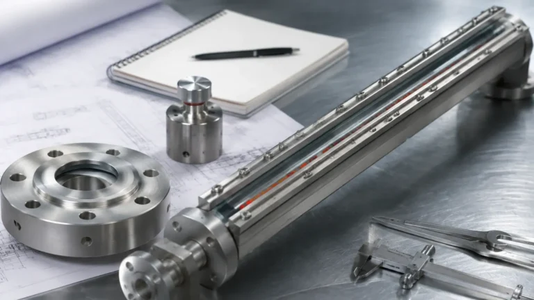
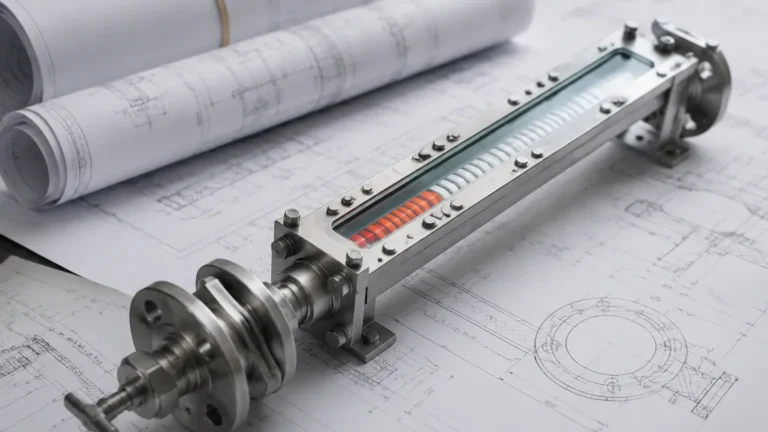
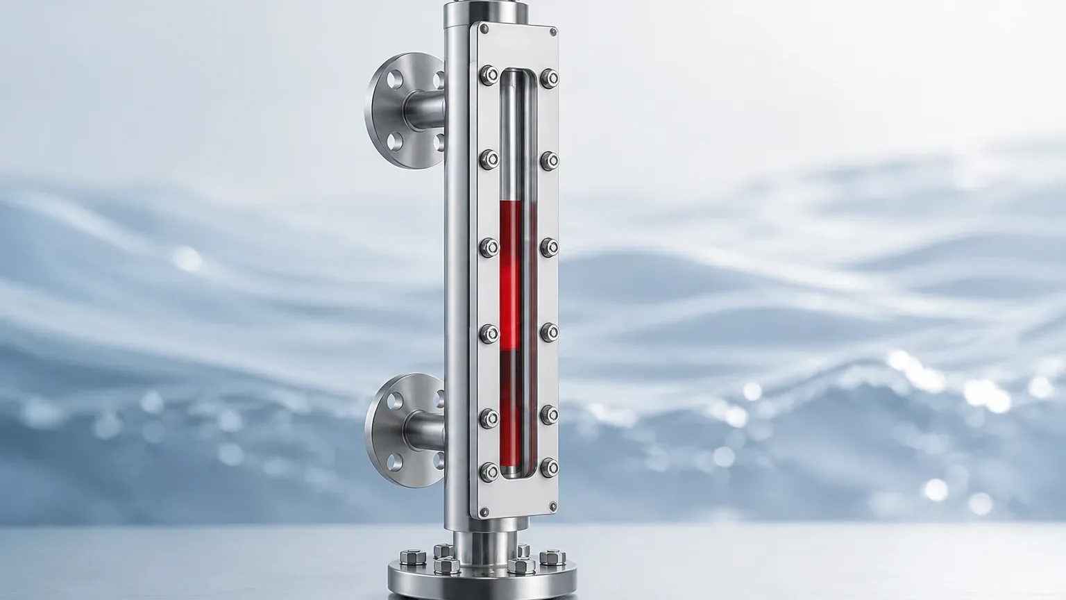
In a magnetic level gauge, the measurement principle evolves from direct sight to magnetic interaction. A float containing a high-intensity permanent magnet is placed inside a non-magnetic bypass chamber. As the liquid level rises and falls, the float moves accordingly. Outside the chamber, a visual indicator—typically consisting of a series of bi-color magnetic flaps or rollers—is mounted.
As the float passes these flaps, the magnetic field causes them to rotate 180 degrees, changing their color (usually from white to red or silver to red). This creates a clear, high-contrast representation of the liquid level. Because the indicator is physically isolated from the process fluid, this method eliminates the risks associated with glass breakage and leaks.
Direct Visual Principles (Glass Gauges)
For applications where direct observation of the fluid is necessary (to check for color, clarity, or foam), glass gauges are used. These operate on two primary optical principles:
1. Reflex Principle: Uses a prism-shaped glass that utilizes light refraction. The liquid-filled area appears dark, while the gas-filled area appears bright/silvery.
2. Transparent Principle: Uses two parallel pieces of flat glass on either side of the fluid, allowing light to pass through the medium for a clear view of the interface or fluid condition.
Types of Local Level Gauges and Their Applications
Choosing a level gauge involves matching the specific gauge design to the operational environment. Below are the most common types found in industrial automation and chemical processing.
Magnetic Level Gauges (MLG)
Magnetic gauges are the preferred choice for high-pressure, high-temperature, or toxic environments. Since the process fluid is entirely contained within a metallic (or plastic) pressure-sealed chamber, there is no risk of glass failure. They are widely used in oil and gas, chemical plants, and power generation.
Reflex Level Gauges
Reflex gauges are designed for clean, non-viscous liquids. The inner surface of the glass has molded prisms. When light hits the gas space, it is reflected back to the observer, appearing bright. When light hits the liquid, it is absorbed/refracted, appearing dark. These are excellent for clear liquids where the interface might otherwise be difficult to see.
Transparent Level Gauges
Transparent gauges are essential when the user needs to see the color of the liquid or when an interface between two different liquids (e.g., oil and water) must be monitored. They are often equipped with illuminators mounted on the back to enhance visibility in dark industrial settings.
Tubular Level Gauges
The simplest form of a level gauge, consisting of a clear tube (usually glass or plastic) protected by a metal guard. These are restricted to low-pressure, non-hazardous applications like water storage tanks or lubricant reservoirs.
Key Evaluation Criteria for Selection
When specifying a level gauge for a project, several technical parameters must be confirmed to ensure safety and accuracy. Use the following table as a preliminary selection guide.
| Feature | Magnetic Level Gauge | Reflex Glass Gauge | Transparent Glass Gauge |
| :— | :— | :— | :— |
| Max Pressure | Up to 400 bar (40 MPa) | Up to 250 bar (25 MPa) | Up to 250 bar (25 MPa) |
| Max Temperature | Up to 450°C | Up to 400°C | Up to 400°C |
| Visibility | Excellent (High Contrast) | Good (Dark/Light) | Fair (Requires Light) |
| Hazardous Fluids | Highly Recommended | Limited | Limited |
| Interface Detection | Possible with specific floats | Difficult | Excellent |
| Maintenance | Low | Moderate (Gasket checks) | Moderate (Cleaning) |
Material Compatibility
The chamber and float materials must be resistant to the process medium. Common materials include:
* 316L Stainless Steel: Standard for water, oils, and mild chemicals.
* Hastelloy/Titanium: For highly corrosive acids or seawater.
* PVC/PP/PVDF: For low-pressure corrosive applications where metals are not suitable.
Fluid Density and Specific Gravity
For magnetic gauges, the float must be engineered to match the specific gravity (SG) of the liquid. If the SG is too low (e.g., liquefied gases), the float must be extremely lightweight yet strong enough to withstand the process pressure without collapsing.
Installation Considerations and Best Practices
Correct installation is vital for the longevity and reliability of a level gauge. Improper mounting can lead to mechanical stress, leaks, or inaccurate readings.
1. Vertical Alignment: The gauge must be installed perfectly vertical. Even a slight tilt can cause the float in a magnetic gauge to rub against the chamber walls, leading to friction and eventual sticking.
2. Isolation Valves: Always install high-quality isolation valves (ball or needle valves) between the vessel and the gauge. This allows for maintenance or replacement without shutting down the entire process. Many industrial standards require "auto-reclosing" check balls in these valves to prevent spills if the gauge is damaged.
3. Venting and Draining: Every gauge installation should include a vent valve at the top and a drain valve at the bottom. This is necessary for clearing debris, sampling the fluid, and safely depressurizing the unit before maintenance.
4. Support Brackets: For gauges with a long center-to-center distance (typically exceeding 2 or 3 meters), intermediate support brackets must be used to prevent vibration and mechanical fatigue on the process connections.
5. Thermal Expansion: In high-temperature applications, the piping and the gauge will expand. The installation design must account for this expansion to avoid putting undue stress on the tank nozzles.
Limitations and Operational Constraints
While highly reliable, every level gauge has limitations that engineers must consider during the design phase.
* Viscosity and Solids: If the liquid is highly viscous or contains suspended solids, the float in a magnetic gauge may become sluggish or stuck. Similarly, solids can coat the glass in a visual gauge, obscuring the view. In such cases, specialized wide-chamber designs or steam jackets may be required.
* Magnetic Interference: Magnetic level gauges should not be installed near large electromagnetic fields or high-power cables, as these can interfere with the magnetic coupling between the float and the indicator.
* Coating and Scaling: Liquids that tend to crystallize or scale can build up inside the chamber. Regular flushing via the drain valve is necessary to maintain performance.
* Extreme Pressures: At extremely high pressures, the density of the gas phase can approach the density of the liquid phase, which affects float buoyancy and can make level detection difficult.
Maintenance and Troubleshooting
To ensure a level gauge provides a reliable reading throughout its service life, a routine maintenance schedule should be implemented.
* Visual Inspection: Check for leaks at gaskets and valves. For glass gauges, look for signs of thinning (erosion) or clouding of the glass.
* Flushing: Periodically open the drain valve to flush out sediment. This is especially important in boiler water applications where sludge can accumulate.
* Float Check: In magnetic gauges, if the indicator stops moving, it may indicate a collapsed float or a build-up of magnetic particles (fines). Magnetic filters can be installed in the process line to mitigate the latter.
Frequently Asked Questions (FAQ)
Q: Can a magnetic level gauge be used for interface measurement between two liquids?
A: Yes. By weighting the float so that its density is between the densities of the two liquids (e.g., oil and water), the float will sink through the top layer and float on the bottom layer, accurately indicating the interface level.
Q: What is the benefit of a "bicolor" indicator?
A: Bicolor indicators (usually red and white) provide high visibility from a distance, even in poor lighting. The color change is definitive, eliminating the ambiguity sometimes found with glass gauges where the liquid might be clear.
Q: How do I choose between a reflex and a transparent glass gauge?
A: Use a reflex gauge for clean, single-phase liquids where you only need to see the level. Use a transparent gauge if the liquid is dirty, viscous, or if you need to observe the color or an interface.
Q: Do magnetic level gauges require power?
A: The basic visual indication is purely mechanical and magnetic, requiring no power. However, you can add reed switches or magnetostrictive transmitters to the outside of the chamber to send a 4-20mA signal to a control room, which would require a power source.
Conclusion
Selecting a level gauge is a critical decision in industrial engineering that impacts both operational efficiency and site safety. Whether opting for the robust isolation of a magnetic gauge or the direct clarity of a glass gauge, understanding the specific demands of the process media and environment is paramount. By adhering to strict selection criteria and following rigorous installation standards, operators can ensure that their level measurement systems provide accurate data for years to come.
For those seeking specific configurations or technical support for their next project, it is advisable to review product options and application support to find a solution tailored to the unique pressures, temperatures, and chemical profiles of their facility.