Level 0 Gauge
Level 0 Gauge
In the hierarchy of industrial automation and process control, the term "Level 0" refers to the field level—the actual physical interface where sensors and actuators interact with the process medium. A level 0 gauge, therefore, represents the primary, local instrument installed directly on a vessel or bypass chamber to provide a direct physical reading of the liquid level. While modern facilities rely heavily on remote transmitters and SCADA systems, the local level gauge remains an indispensable safety and verification tool.
For engineers and plant operators, the level 0 gauge serves as the "source of truth." It operates independently of power supplies and control loops, ensuring that even during a total plant power failure or a digital signal error, the actual status of a tank’s contents is visible to personnel on the ground. This guide explores the principles, selection criteria, and technical nuances of Magnetic & Local Level Gauges and their role as foundational instruments in industrial environments.
Measurement Principles of Local Level Gauges
To understand the reliability of a level 0 gauge, one must first understand the physics governing its operation. Most local gauges rely on two fundamental principles: the law of communicating vessels and the principle of buoyancy.
The Law of Communicating Vessels
In traditional glass or reflex gauges, the instrument is connected to the side of a tank via top and bottom process connections. According to the law of communicating vessels, a liquid in a system of interconnected containers will maintain the same level in all containers, provided the pressure and density remain constant. This allows the liquid level in the gauge's sight glass to mirror the level inside the main vessel exactly.
The Buoyancy and Magnetic Coupling Principle
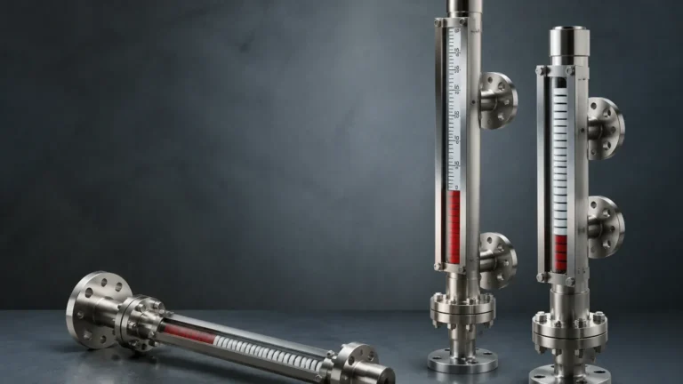
In a magnetic level gauge, the principle of buoyancy (Archimedes' Principle) is combined with magnetic force. A float, specifically engineered to match the density (specific gravity) of the process liquid, sits inside a non-magnetic bypass chamber. As the liquid level rises or falls, the float moves accordingly.
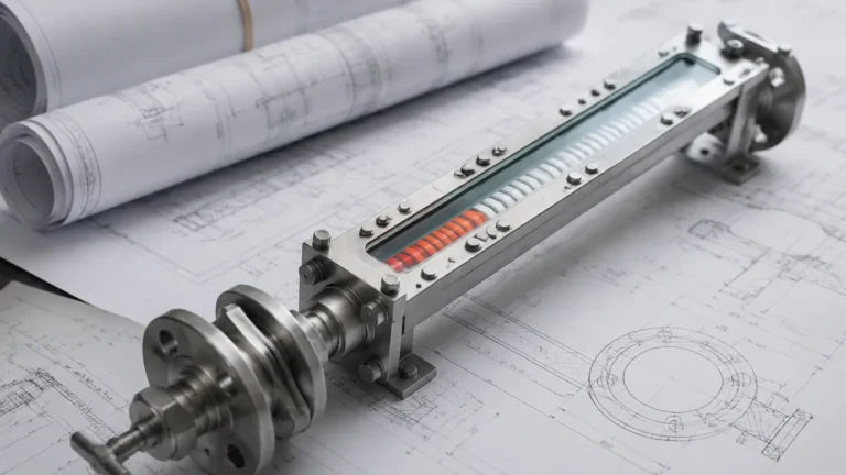
Inside the float is a high-intensity permanent magnet assembly. Outside the chamber, a visual indicator—typically consisting of a series of bi-color magnetic flaps or a follower—is mounted. The magnetic field from the float penetrates the chamber wall and couples with the indicator. As the float moves, the flaps flip 180 degrees, changing color (usually from white to red) to provide a clear, high-contrast visual representation of the level. This method eliminates the risks associated with fragile glass and high-pressure leaks.
Types of Level 0 Gauges
Selecting the correct level 0 gauge requires an understanding of the different technologies available and their specific application strengths.
| Gauge Type | Operating Principle | Best For | Limitations |
| :— | :— | :— | :— |
| Reflex Glass Gauge | Light refraction through prismatic glass. | Clean, non-viscous liquids; clear visibility of colorless liquids. | Not suitable for interface measurement or dirty fluids. |
| Transparent Glass Gauge | Direct observation through two sheets of glass. | Interface measurement; observing color/clarity; high-pressure steam. | Glass is susceptible to chemical etching and thermal shock. |
| Magnetic Level Gauge | Magnetic coupling between a float and an external indicator. | Hazardous, toxic, or high-pressure fluids; long-distance visibility. | Limited by fluid density and the presence of magnetic particles. |
| Tubular Glass Gauge | Direct observation in a glass tube. | Low-pressure, non-hazardous applications (e.g., water tanks). | Very fragile; limited pressure/temperature range. |
Technical Selection Criteria for Magnetic & Local Level Gauges
When specifying a level 0 gauge for a project, several critical parameters must be evaluated to ensure accuracy and safety. Because these instruments are often the last line of defense in manual monitoring, their configuration must be precise.
1. Specific Gravity (Density)
For magnetic gauges, the float is the most critical component. It must be buoyant enough to float on the surface of the liquid but heavy enough to remain stable. If the specific gravity (SG) of the liquid changes—due to temperature fluctuations or chemical composition changes—the float may sink or ride too high, leading to measurement errors. Standard floats are typically designed for SGs ranging from 0.4 to 2.0.
2. Pressure and Temperature Ratings
Unlike electronic sensors that may have remote seals, a level 0 gauge is a pressure-containing vessel. It must be rated for the maximum allowable working pressure (MAWP) and temperature of the main tank. High-temperature applications (above 250°C) require specialized magnetic materials that do not lose their magnetism (Curie point considerations) and cooling extensions for the indicator.
3. Material Compatibility
The chamber, float, and gaskets must be chemically compatible with the process media. Common materials include:
* 316/316L Stainless Steel: The standard for most water and chemical applications.
* Hastelloy or Titanium: For highly corrosive acids or seawater.
* Plastic (PVC/CPVC/PVDF): For low-pressure corrosive applications where metals are unsuitable.
* PTFE Lining: Used within stainless steel chambers to combine structural strength with chemical resistance.
4. Visibility and Measuring Range
The "Level 0" designation implies that the gauge must be readable by a human operator. Consider the distance from which the gauge will be viewed. Magnetic gauges with large, fluted flaps are often visible from 30 meters (approx. 100 feet) or more, whereas reflex glass gauges require closer inspection.
Installation and Engineering Considerations
Correct installation is paramount to the performance of a level 0 gauge. Failure to follow engineering best practices can result in mechanical failure or inaccurate readings.
Orientation and Alignment
The gauge must be installed perfectly vertical. Even a slight tilt can cause the float in a magnetic gauge to rub against the chamber walls, leading to friction and eventual "sticking." For glass gauges, misalignment can put uneven stress on the glass, leading to premature failure or leaks.
Isolation and Venting
Every level 0 gauge should be installed with isolation valves (typically ball or needle valves) at the top and bottom process connections. This allows for maintenance or replacement without draining the main vessel. Additionally, a vent plug at the top and a drain plug at the bottom are essential for commissioning and cleaning the chamber.
Steam Jacketing and Insulation
For liquids that solidify or become highly viscous at ambient temperatures (such as bitumen or certain waxes), steam jacketing or electric heat tracing is required. This ensures the liquid inside the gauge remains at the same temperature and state as the liquid in the tank.

Limitations and Risks
While highly reliable, no instrument is without limitations. For a level 0 gauge, the following risks must be managed:
* Magnetic Particles: In magnetic gauges, if the process fluid contains ferrous particles (e.g., pipe scale or magnetite), these particles will be attracted to the float's magnets. This buildup can eventually jam the float. In such cases, a magnetic trap should be installed upstream of the gauge.
* Flash Evaporation: If a liquid is near its boiling point, a sudden drop in pressure within the gauge chamber can cause "flashing." The resulting gas bubbles can cause the float to bounce or give erratic readings in a glass gauge.
* Coating and Scaling: Highly viscous or "sticky" fluids can coat the inside of a glass gauge or the float of a magnetic gauge. Regular maintenance and the use of specialized coatings (like PFA) can mitigate this, but extremely heavy sludges may require alternative technologies like radar.
Maintenance Best Practices
A level 0 gauge is often a "fit and forget" instrument, but periodic inspection is necessary for safety compliance:
1. Visual Inspection: Check for leaks at gaskets and valves. Ensure the indicator flaps are clean and moving freely.
2. Flushing: Periodically open the drain valve to flush out any sediment that may have accumulated in the bottom of the chamber.
3. Float Verification: For magnetic gauges, a simple test with an external magnet can verify that the internal float is moving freely and the indicator is responding correctly.
Frequently Asked Questions (FAQ)
Q: Can a level 0 gauge provide an electronic signal for a control room?
A: Yes. While their primary function is local indication, magnetic level gauges can be equipped with reed switches (for point level detection) or magnetostrictive transmitters (for continuous 4-20mA/HART output). This allows the gauge to serve as both a Level 0 visual reference and a Level 1 data source.
Q: What is the maximum length for a local level gauge?
A: Standard lengths usually go up to 6 meters (approx. 20 feet). For taller tanks, gauges are often manufactured in sections and joined with flanges to ensure structural integrity and ease of transport.
Q: How do I choose between a reflex and a transparent glass gauge?
A: Use a reflex gauge for clean, single-phase liquids where you need a high-contrast "black/silver" interface. Use a transparent gauge if you need to see the actual color of the liquid, if you are measuring the interface between two different liquids (like oil and water), or for high-pressure steam applications where a mica shield is needed to protect the glass.
Q: Is a level 0 gauge suitable for sanitary applications?
A: Yes, but they must be specifically designed with tri-clamp fittings, polished internal surfaces (Ra < 0.8 µm), and materials that meet FDA or 3-A standards to prevent bacterial growth.
By prioritizing the selection and maintenance of the level 0 gauge, industrial facilities ensure a robust layer of protection and a reliable physical reference for their most critical process vessels. Whether using a simple sight glass or a sophisticated magnetic system, these instruments remain the cornerstone of field-level monitoring.