5 Level Gauge
5 Level Gauge
In industrial process control, the term "5 level gauge" frequently refers to level measurement systems configured to monitor five critical setpoints or those designed for standard 5-meter vessel heights. Whether used for simple visual verification or integrated into a complex SCADA system, Magnetic & Local Level Gauges remain the industry standard for reliable, power-free liquid level indication.
This guide explores the engineering principles, selection criteria, and installation requirements for these instruments, focusing on how a multi-point or 5-level configuration enhances operational safety and efficiency in sectors ranging from water treatment to chemical processing.
Measurement Principles of Local Level Gauges
Before selecting a specific gauge configuration, it is essential to understand the physics governing their operation. Most local level indicators rely on the principle of "communicating vessels."
The Law of Communicating Vessels
According to hydrostatic physics, when a liquid is at rest in connected containers, the liquid level remains the same in each container, regardless of their shape or volume. A level gauge is essentially a bypass chamber connected to the side of a tank. As the liquid level rises or falls in the main vessel, it moves identically within the gauge chamber.
Magnetic Coupling Principle
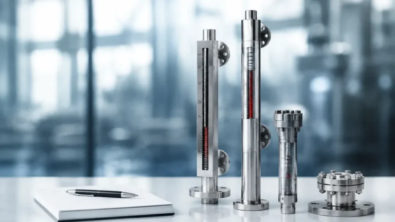
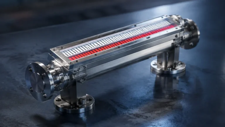
In a magnetic level gauge, a float containing a high-intensity permanent magnet is placed inside the chamber. This float is engineered to have a specific buoyancy that matches the density of the process media. Outside the chamber, a column of bi-color (usually red and white) magnetic flaps or a magnetic follower is mounted.
As the float moves with the liquid level, the magnetic field passes through the non-magnetic chamber wall (usually stainless steel or plastic) and rotates the flaps 180 degrees. This provides a clear, high-contrast visual representation of the level without the need for a glass window that could leak or cloud over time.
Multi-Point Sensing (The 5-Level Configuration)
When engineers specify a "5 level gauge," they are often referring to a magnetic gauge equipped with five magnetic reed switches or a continuous transmitter calibrated for five specific alarm/control points:
1. Low-Low (LL): Emergency shutdown or pump dry-run protection.
2. Low (L): Pump start or refill request.
3. Normal (N): The optimal operating range.
4. High (H): High-level alert or valve closure signal.
5. High-High (HH): Overfill prevention and emergency vent activation.
Key Types of Local Level Gauges
While magnetic gauges are the most versatile, other local indicators serve specific niche applications. Understanding the differences is crucial for proper procurement.
| Gauge Type | Operating Principle | Best Use Case | Limitations |
| :— | :— | :— | :— |
| Magnetic Level Gauge | Magnetic float & flaps | Corrosive, high-pressure, or toxic media | Requires specific gravity > 0.45 |
| Reflex Glass Gauge | Light refraction in glass | Clean liquids, steam boilers | Glass can break; difficult to read at a distance |
| Transparent Glass Gauge | Direct vision through two plates | Interface measurement (oil/water) | Requires frequent cleaning |
| Tubular Glass Gauge | Direct vision in a glass tube | Low-pressure, non-hazardous tanks | Low mechanical strength; safety risk |
| Level Switch Array | Multiple reed or float switches | Discrete 5-point level control | No continuous visual indication |
Technical Selection Criteria for a 5 Level Gauge
Selecting the right instrument requires a detailed analysis of the process environment. A mismatch between the gauge material and the process fluid can lead to catastrophic failure.
1. Material Compatibility
The wetted parts (chamber and float) must be chemically resistant to the media.
* 304/316L Stainless Steel: Standard for water, oil, and mild chemicals.
* PVC/PP/PVDF: Ideal for highly corrosive acids or plating baths where metals would corrode.
* Titanium or Hastelloy: Used in extreme chemical environments or high-temperature applications.
2. Pressure and Temperature Ratings
Standard magnetic gauges can handle pressures up to 10 MPa (approx. 1450 PSI) and temperatures up to 400°C (752°F). For a 5-meter tank, the weight of the liquid column and the internal vapor pressure must be calculated to ensure the chamber wall thickness is sufficient.
3. Specific Gravity (Density)
The float is the heart of the system. It must be lighter than the liquid to float but heavy enough to remain stable. If the specific gravity of the liquid changes (e.g., due to temperature fluctuations), the float may sink or sit too high, leading to measurement errors. Most 5 level gauges are custom-weighted to the exact density of the process fluid.
4. Visibility and Scaling
For a gauge spanning 5 meters (approx. 16.4 feet), visibility from a distance is paramount. Magnetic flaps are typically 10mm to 20mm wide, allowing operators to read the level from 30 meters away. Scales should be provided in metric (mm/cm) or percentage units, depending on the plant's standard operating procedures.
Installation Considerations
Proper installation is as important as the selection of the instrument itself. For a 5 level gauge, especially long units, the following steps are mandatory:
* Verticality: The gauge must be installed perfectly vertical. Even a slight tilt can cause the float to frictionally bind against the chamber wall, leading to "stuck" readings.
* Support Brackets: For gauges exceeding 3 meters (approx. 10 feet) in length, intermediate support brackets are required to prevent vibration and mechanical stress on the process flanges.
* Isolation Valves: Always install isolation valves between the tank and the gauge. This allows for maintenance and cleaning without draining the entire vessel.
* Clearance: Ensure there is enough overhead or bottom clearance to remove the float for inspection. If space is limited, top-mounted magnetic gauges may be an alternative.
* Magnetic Interference: Keep the gauge away from large motors, transformers, or high-voltage cables, as strong external magnetic fields can interfere with the float-to-flap coupling.

Maintenance and Troubleshooting
Local level gauges are favored for their low maintenance requirements, but they are not "set and forget" devices.
1. Flushing: Periodically use the drain valve at the bottom of the chamber to flush out sediment or scale. This is especially important in water treatment or heavy oil applications.
2. Float Inspection: Once a year, remove the float to check for pitting, corrosion, or the accumulation of magnetic particles (iron filings) which can weigh the float down.
3. Flap Alignment: If a flap becomes stuck due to mechanical shock, a simple external magnet can be run along the rail to reset the flags to their correct orientation.
Limitations of Local Level Gauges
While highly reliable, these gauges have specific boundaries:
* Coating/Caking: If the process media is extremely viscous or prone to crystallization, it can coat the float and chamber, causing the float to stick.
* High Vibration: Excessive mechanical vibration can cause the magnetic flaps to flip prematurely. In these cases, dampened flaps or electronic transmitters are preferred.
* Magnetic Particles: If the fluid contains high concentrations of iron filings, they will stick to the internal magnet of the float, eventually preventing movement.
Frequently Asked Questions (FAQs)
Q: Can a 5 level gauge be used for hazardous areas?
A: Yes. Since the primary indication is mechanical/magnetic, it is inherently explosion-proof. If electronic switches or transmitters are added for the 5-level control, they must be rated (e.g., ATEX or SIL2) for the specific hazardous zone.
Q: How do I calibrate a magnetic level gauge?
A: Magnetic gauges do not require traditional calibration because they rely on physical buoyancy. However, the zero point must be verified against the tank's bottom datum, and any attached electronic transmitters should be calibrated using a standard 4-20mA loop calibrator.
Q: What is the maximum length for a single-piece gauge?
A: Most manufacturers can produce single-piece chambers up to 6 meters (approx. 20 feet). For heights exceeding this, the gauge is typically manufactured in sections and joined with flanges to ensure structural integrity during transport and installation.
Q: Can I use one gauge for two different liquids (interface)?
A: Yes, provided there is a sufficient density difference (usually >0.1 g/cm³). The float is weighted to sink through the upper liquid and float on the lower liquid, indicating the interface level.
Conclusion
Whether you are managing a 5-meter storage tank or require a precise 5-point alarm system, Magnetic & Local Level Gauges provide the durability and clarity needed for industrial environments. By understanding the buoyancy principles and selecting materials that match the chemical profile of your media, you can ensure a long-service life with minimal maintenance. Always consult with a technical specialist to confirm that the float design and chamber pressure ratings meet your specific project safety standards.