Level Gauge K Tek
Level Gauge K Tek
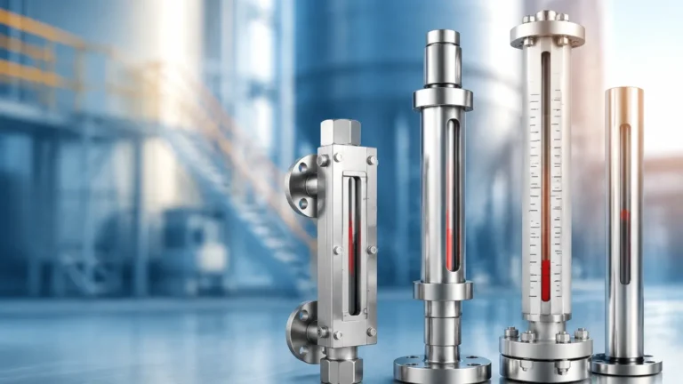
In the landscape of industrial liquid level measurement, the term "level gauge K Tek" often serves as a benchmark for high-performance magnetic level indicators (MLIs). K-TEK, a brand historically recognized for its robust engineering in magnetic level gauges, established many of the industry standards for reliability in high-pressure and high-temperature environments. Today, engineers looking for "level gauge K Tek" solutions are typically seeking the same level of precision, safety, and durability for their bypass level measurement needs.
As a professional manufacturer, Welk continues this tradition of engineering excellence by providing Magnetic & Local Level Gauges designed to meet the rigorous demands of modern industrial automation, water treatment, and chemical processing. This guide explores the principles, selection criteria, and installation best practices for these essential instruments.
Measurement Principles of Magnetic Level Gauges
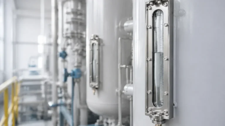
The fundamental operation of a magnetic level gauge is based on two physical principles: buoyancy and magnetism. Unlike traditional glass sight gauges, which expose the process fluid to a fragile glass tube, a magnetic level gauge uses a robust metal bypass chamber.
The Buoyancy Principle
Inside the bypass chamber (usually mounted to the side of a tank), a float is designed to have a density lower than the process liquid. According to Archimedes' principle, the float will remain partially submerged and rise or fall precisely with the liquid level. The engineering challenge lies in the float design; it must be light enough to float in low-density liquids (such as liquefied gases) while being strong enough to withstand high process pressures without collapsing.
Magnetic Coupling
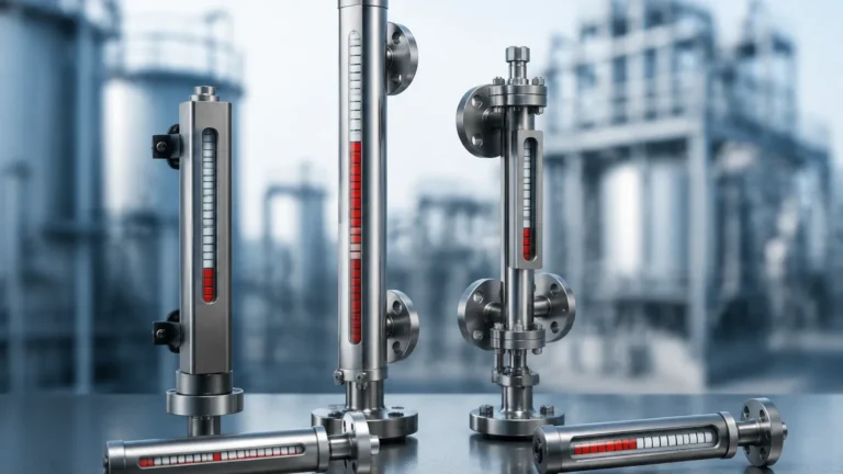
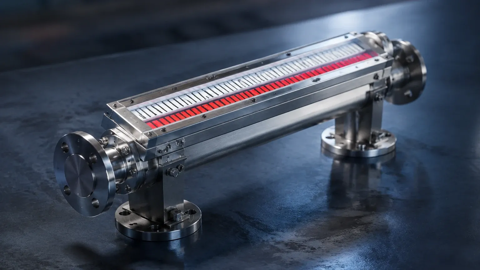
Inside the float is a high-intensity 360° magnetic ring. Outside the chamber, an indicator rail is attached. This rail contains either a series of bi-color magnetic flappers or a moving shuttle. As the float moves with the liquid level, its internal magnetic field couples with the external indicators through the non-magnetic chamber wall (typically stainless steel or alloy). This causes the flappers to rotate—usually from white to red—providing a clear, high-visibility local level indication without any direct contact between the process fluid and the indicator.
Why Engineers Specify Level Gauge K Tek Standards
The search for a "level gauge K Tek" often stems from the brand's history of solving complex application issues. When selecting a magnetic level gauge, engineers prioritize the following characteristics that K-TEK popularized:
1. Safety in High Pressure: Traditional glass gauges are prone to leaks and catastrophic failure under pressure. Magnetic gauges provide a hermetic seal, making them ideal for toxic or flammable media.
2. Low Maintenance: Because the indicator is isolated from the process fluid, there is no clouding, scaling, or leaking associated with the visual display.
3. Versatility: These gauges can be outfitted with reed switches for point level control or magnetostrictive transmitters for continuous 4-20mA or HART output, effectively turning a local gauge into a sophisticated level transmitter.
Practical Selection Criteria
Choosing the right instrument requires a detailed understanding of the process conditions. The following table provides a general framework for evaluating Magnetic & Local Level Gauges based on typical industrial requirements.
Selection Table: Magnetic Level Gauge Specifications
| Feature | Standard Industrial | High Pressure/Temp | Corrosive Media |
| :— | :— | :— | :— |
| Chamber Material | 304/316L Stainless Steel | Hastelloy C / Titanium | PTFE/PFA Lined SS |
| Max Pressure | 40 bar (580 psi) | Up to 320 bar (4641 psi) | 16 bar (232 psi) |
| Max Temperature | 150°C (302°F) | Up to 450°C (842°F) | 120°C (248°F) |
| Min Specific Gravity | 0.80 | 0.45 | 0.90 |
| Connection Type | Flanged (ANSI/DIN) | Welded / High-Pressure Flange | Plastic/Lined Flange |
Fluid Density (Specific Gravity)
Specific gravity (SG) is the most critical factor. A float designed for water (SG 1.0) will not work in a light hydrocarbon (SG 0.6). Welk custom-engineers floats to match the exact SG of the process fluid, ensuring the magnetic ring aligns perfectly with the liquid surface.
Material Compatibility
For standard water treatment, 304 or 316 stainless steel is sufficient. However, in chemical applications involving acids or chlorides, materials like Hastelloy C-276 or Titanium are required to prevent pitting and stress corrosion cracking. For highly aggressive acids where no metal is suitable, PTFE-lined chambers are the preferred solution.
Installation Considerations
Proper installation is paramount for the long-term reliability of a magnetic level gauge. Unlike simple sensors, these are mechanical assemblies that require precise alignment.
1. Vertical Alignment: The chamber must be installed perfectly vertical. Any tilt can cause the float to frictionally bind against the chamber walls, leading to inaccurate readings or a "stuck" float.
2. Magnetic Interference: Since the gauge relies on magnetic coupling, it must be kept away from large ferrous structures or high-voltage power lines that could create electromagnetic interference. Standard practice suggests a minimum clearance of 100mm (4 inches) from carbon steel supports.
3. Bypass Piping: Ensure that the isolation valves used for the side-mount connections are full-port valves. This prevents debris from clogging the entry points to the chamber.
4. Venting and Draining: Every installation should include a vent valve at the top and a drain valve at the bottom. This allows for safe commissioning and the ability to flush the chamber during maintenance cycles.
Limitations and Operational Boundaries
While magnetic level gauges are exceptionally versatile, they do have factual limitations that engineers must consider:
* Particulate Matter: If the process fluid contains magnetic particles (such as iron filings or magnetite), these particles will adhere to the float's internal magnet. Over time, this buildup will increase the float's weight and eventually cause it to sink or jam. In such cases, a magnetic trap should be installed in the bypass line.
* Coating and Viscosity: Highly viscous liquids or those that tend to crystallize can impede the movement of the float. While steam jackets can be added to maintain fluid temperature and reduce viscosity, extremely "sticky" media may be better suited for non-contact ultrasonic or radar level sensors.
* Extreme Cold: In cryogenic applications, frost buildup on the indicator rail can obscure the flappers. Specially designed frost-proof extensions are required to keep the indicator clear of ice.
Maintenance and Troubleshooting FAQ
Q: Why is my indicator showing a different level than my control system?
A: First, verify the specific gravity of the liquid. If the density has changed due to temperature fluctuations, the float may be sitting lower or higher in the liquid than calibrated. Second, check for magnetic debris in the chamber.
Q: Can I add a transmitter to my existing gauge later?
A: Yes. One of the primary advantages of the "level gauge K Tek" style design is modularity. You can strap a magnetostrictive transmitter to the outside of the chamber without interrupting the process or breaking the pressure seal.
Q: How often should the float be inspected?
A: In clean service, floats can last for decades. In corrosive or scaling service, an annual inspection is recommended. Use the drain valve to flush the chamber; if the indicator follows the level down and back up smoothly, the float is functioning correctly.
Conclusion
Whether you are replacing an existing "level gauge K Tek" unit or designing a new system from the ground up, understanding the interplay between buoyancy and magnetic coupling is essential. By selecting the correct materials and ensuring precise installation, magnetic level gauges provide one of the most reliable and low-maintenance methods for local level indication in the industry.
For technical support in selecting the appropriate Magnetic & Local Level Gauges for your specific application, consult with engineering experts who can provide customized float designs and chamber configurations tailored to your process density and pressure requirements.