Local Level Gauge
Local Level Gauge
In industrial process control, the local level gauge remains an indispensable component for tank and vessel monitoring. While digital transmitters and remote sensors provide the data necessary for automated control loops, a local level gauge serves as the primary visual reference and a critical safety redundancy. These instruments allow operators to verify liquid levels directly at the tank site without relying on electrical power or complex control systems.
This guide explores the fundamental principles, technical specifications, and selection criteria for various local level measurement technologies, with a particular focus on the robust performance of magnetic and glass-based systems used in water treatment, chemical processing, and oil and gas industries.
Measurement Principles of Local Level Gauges
Local level measurement is generally based on two physical principles: the law of communicating vessels (Pascal's Law) and buoyancy.
The Law of Communicating Vessels
Most local level gauges, such as tubular and glass gauges, operate by connecting a bypass chamber or tube to the side of a vessel. According to Pascal’s Law, a liquid in a system of connected containers will reach the same level in all containers, provided the pressure above the liquid remains equal. By installing a transparent tube or a chamber with a viewing window parallel to the tank, the liquid level inside the gauge matches the level inside the tank, allowing for direct visual inspection.
The Buoyancy Principle
Magnetic level gauges utilize Archimedes' principle. A float is designed with a specific density to remain buoyant on the surface of the process liquid. This float contains an internal magnet assembly. As the liquid level changes, the float moves up and down within a non-magnetic chamber. The magnetic field from the float interacts with an external indicator (usually a series of bi-color flaps or a follower), providing a visual representation of the level without the liquid ever coming into contact with the viewing glass or indicator.
Primary Types of Local Level Gauges
Choosing the correct local level gauge requires an understanding of the specific strengths and limitations of each technology.
1. Tubular Level Gauges
This is the simplest form of a local level gauge. It consists of a transparent tube (usually glass or plastic) connected to the tank via valves.
* Application: Low-pressure, non-hazardous liquids at ambient temperatures.
* Limitations: The glass is exposed and prone to breakage; not suitable for high-pressure or toxic media.
2. Reflex Glass Gauges
Reflex gauges use a specially grooved glass that utilizes light refraction. The grooves are designed to absorb light in the liquid phase and reflect light in the gas/vapor phase.
* Visual Effect: The liquid appears dark (black), while the vapor space appears bright (silver/white).
* Best Use: Clear liquids where the interface between liquid and gas needs high contrast.
3. Transparent Glass Gauges
Transparent gauges feature two pieces of flat glass on opposite sides of the chamber. This allows light to pass through the medium.
* Visual Effect: The operator looks through the liquid.
* Best Use: Interface measurement (detecting the line between two different liquids), dirty fluids, or applications requiring an illuminator for night viewing.
4. Magnetic Level Gauges
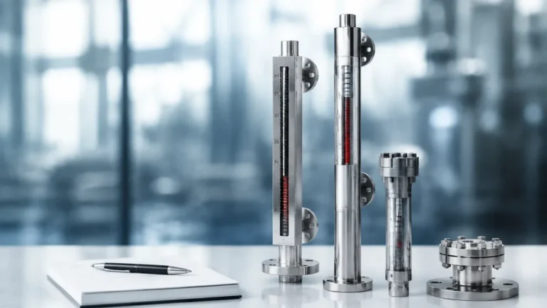
For modern industrial applications, Magnetic & Local Level Gauges have become the industry standard for safety and reliability. Because the process fluid is entirely contained within a pressure-rated metal chamber, there is no risk of glass breakage or leakage of hazardous materials.
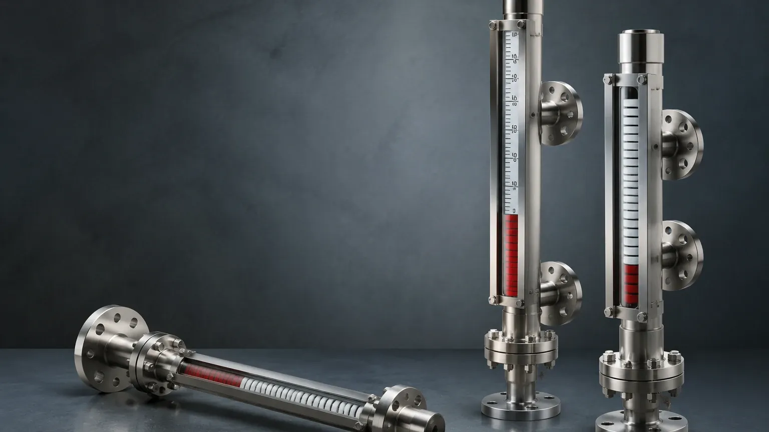
* Visual Effect: A column of bi-color magnetic flaps (typically red and white) flips as the float passes, creating a highly visible bar graph.
* Best Use: High pressure, high temperature, toxic, or corrosive media.
Technical Selection Criteria
Selecting a local level gauge is a critical engineering decision that impacts both plant safety and operational efficiency. The following table provides a comparison of typical operating boundaries.
| Feature | Tubular Gauge | Reflex/Transparent Glass | Magnetic Level Gauge |
| :— | :— | :— | :— |
| Max Pressure | Up to 10 bar | Up to 250 bar | Up to 400+ bar |
| Max Temperature | Up to 100°C | Up to 400°C | Up to 530°C |
| Visibility | Moderate | Good | Excellent (Long distance) |
| Hazardous Media | Not Recommended | Restricted | Highly Recommended |
| Maintenance | High (Cleaning) | Medium (Gasket leaks) | Low (Self-cleaning floats) |
Material Compatibility
The wetted parts of the gauge must be compatible with the process media. Standard materials include 316L Stainless Steel, but for corrosive applications, materials such as Hastelloy, Monel, or plastic linings (PTFE/PFA) are required. For the float in a magnetic gauge, titanium is often used due to its high strength-to-weight ratio, allowing it to remain buoyant even in low-density fluids (down to 0.35 g/cm³).
Process Conditions
* Specific Gravity: The float in a magnetic gauge must be weighted specifically for the liquid's density. If the density changes significantly due to temperature fluctuations, the accuracy of the local level gauge may be affected.
* Viscosity: Highly viscous liquids may impede the movement of a float or coat the inside of a glass gauge, making it difficult to read.
* Pressure and Temperature: These dictate the flange ratings (e.g., ANSI 150#, 300#, 600#) and the thickness of the glass or chamber walls.
Installation and Commissioning Considerations
Proper installation is essential for the accuracy and longevity of a local level gauge. Engineers should follow these practical guidelines:
1. Vertical Alignment: The gauge must be installed perfectly vertical. Any tilt can cause the float to rub against the chamber walls in magnetic gauges, leading to friction and inaccurate readings.
2. Isolation Valves: Always install high-quality isolation valves (ball or needle valves) between the tank and the gauge. This allows for maintenance and cleaning without draining the entire vessel.
3. Venting and Draining: Ensure the gauge has a vent plug at the top and a drain valve at the bottom. This is necessary for clearing air pockets during commissioning and for flushing out sediment during maintenance.
4. Center-to-Center (C-C) Distance: This is the precise distance between the mounting flanges. Accurate measurement of the C-C distance is the most critical step when ordering a replacement or a new unit to ensure it fits the existing tank nozzles.
5. Support Brackets: For gauges exceeding 3 meters (3000 mm) in length, intermediate support brackets should be used to prevent vibration and mechanical stress on the process connections.
Limitations of Local Level Gauges
While highly reliable, local level gauges have specific limitations that must be managed:
* Coating and Scaling: In glass gauges, the buildup of scale or film on the interior surface can eventually obscure the liquid level. In magnetic gauges, magnetic particles (such as iron filings) in the fluid can attach to the float, increasing its weight and causing it to sink or stick.
* Fluid Density Sensitivity: Because magnetic gauges rely on buoyancy, they are calibrated for a specific density. If a tank is used for multiple different chemicals with varying densities, the gauge may require a different float for each media.
* Mechanical Wear: Over many years, floats can suffer from metal fatigue or corrosion, and glass can become etched (especially in steam applications), requiring periodic replacement.
Maintenance and Safety Protocols
To ensure the local level gauge remains a reliable safety device, a routine maintenance schedule should be implemented:
* Visual Inspection: Check for leaks at gaskets and flange connections. For glass gauges, look for signs of thinning or clouding of the glass.
* Flushing: Use the drain valve to flush the chamber periodically. This prevents the accumulation of solids that could jam the float or obscure the sight glass.
* Float Check: In magnetic gauges, ensure the float moves freely by slowly draining and refilling the chamber. If the indicator flips smoothly, the float is functioning correctly.
* Glass Protection: In steam or high-pressure water applications, use mica shields to protect transparent glass from the corrosive effects of alkaline water.
Frequently Asked Questions (FAQ)
Q: Can a local level gauge provide a 4-20mA signal to a PLC?
A: Yes. While the primary function is local visual indication, magnetic level gauges can be equipped with external reed chain transmitters or magnetostrictive sensors that provide a continuous 4-20mA or HART signal without breaking the pressure boundary.
Q: How do I read a reflex gauge if the liquid is colorless?
A: The reflex glass is designed specifically for this. Even if the liquid is as clear as water, the prismatic grooves will make the liquid-filled portion appear black and the vapor portion appear silver. No coloring agents are needed.
Q: What happens if the float in a magnetic gauge is installed upside down?
A: The gauge will not function correctly. The magnet assembly inside the float is positioned to align with the external indicator. Most floats are clearly marked with a "TOP" arrow to prevent this installation error.
Q: Are local level gauges suitable for cryogenic applications?
A: Yes, but they require specialized insulation and "frost-extension" blocks. These extensions prevent ice from forming over the viewing area, ensuring the level remains visible even at temperatures as low as -196°C.
Q: What is the maximum length for a single-piece local level gauge?
A: Most manufacturers can produce single-piece magnetic gauges up to 6 meters. For taller tanks, gauges are typically manufactured in sections and joined with flanges to facilitate shipping and installation.
By understanding the physical principles and technical requirements of the local level gauge, engineers can ensure they select a solution that provides accurate, maintenance-free visual monitoring for the life of the process plant.