Z Gauges
Z Gauges
In the field of industrial process control, the ability to verify liquid levels locally remains a critical safety and operational requirement. While electronic sensors provide data to control rooms, local level indicators—often referred to in specific engineering circles as Z gauges or offset-style gauges—provide a mechanical, fail-safe point of reference. These instruments are essential for verifying the accuracy of automated systems and ensuring manual oversight during startup, shutdown, or power loss scenarios.
Understanding the nuances of Magnetic & Local Level Gauges is vital for engineers designing storage tanks, pressure vessels, and bypass systems. This guide explores the mechanical principles, selection criteria, and practical application of these instruments in modern industrial environments.
Understanding the Principles of Local Level Measurement
Local level measurement relies on the fundamental law of communicating vessels. This principle states that a liquid in a set of connected containers will reach the same level in all containers, regardless of their shape or volume, provided the pressure remains constant across the surface of the liquid.
In a standard installation, a gauge chamber is mounted to the side of a vessel via two process connections: one at the top (vapor space) and one at the bottom (liquid space). The liquid level in the chamber mirrors the level inside the vessel, allowing for direct or indirect observation.
The "Z" Configuration and Offset Design
The term "Z gauges" typically refers to a specific physical arrangement of the gauge valves and the sight chamber. In a Z-type or offset configuration, the centerlines of the process connections are not aligned directly with the centerline of the gauge glass or chamber. Instead, the valves are offset to the side.
This design offers several practical advantages:
1. Ease of Cleaning: A cleaning brush can be passed through the gauge chamber by removing the vent and drain plugs without removing the gauge from the vessel.
2. Glass Replacement: In glass-style gauges, the offset allows for easier access to the glass and gaskets during maintenance.
3. Safety: If a glass tube breaks, the offset valves often incorporate ball-check safety mechanisms that are more effective in this geometry.
Key Types of Magnetic & Local Level Gauges
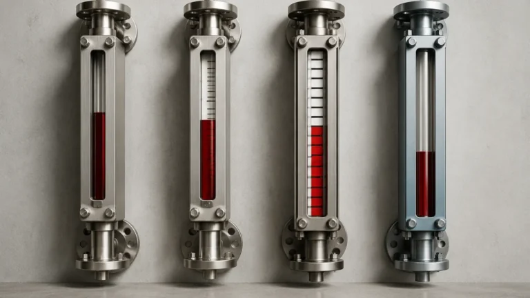
When selecting a local indicator, engineers must choose between direct-view glass gauges and indirect-view magnetic gauges. Each has specific use cases depending on the pressure, temperature, and toxicity of the fluid.
1. Reflex Level Gauges
Reflex gauges use a special prism-shaped glass. The principle is based on light refraction and reflection. When light enters the glass in the vapor space, it is reflected back to the observer, appearing bright white. When light hits the liquid-filled portion, it is refracted into the liquid, making that section appear dark or black. This high-contrast display is ideal for clean, low-viscosity liquids.
2. Transparent Level Gauges
These gauges feature two pieces of flat glass on opposite sides of the chamber. This allows light to pass through the liquid, making it possible to observe the color, interface, or clarity of the fluid. Transparent gauges are often used for interface measurement (e.g., oil and water) or for highly corrosive fluids where the glass must be protected by a mica shield.
3. Magnetic Level Gauges
Magnetic level gauges are the preferred choice for high-pressure or hazardous applications. They consist of a non-magnetic bypass chamber containing a float with an internal permanent magnet. As the float rises and falls with the liquid level, the magnetic field acts upon an external indicator—typically a series of bi-colored magnetic flaps or a follower capsule. Because the fluid is completely contained within the metal chamber, there is no risk of glass breakage or leakage into the environment.
Selection Criteria for Z Gauges and Local Indicators
Choosing the right gauge requires an evaluation of the process media and the environmental conditions. The following table provides a comparison of common selection factors for Magnetic & Local Level Gauges.
| Feature | Reflex Glass Gauges | Transparent Glass Gauges | Magnetic Level Gauges |
| :— | :— | :— | :— |
| Max Pressure | Up to 250 bar (25 MPa) | Up to 340 bar (34 MPa) | Up to 400+ bar (40+ MPa) |
| Max Temperature | 400°C (with limitations) | 400°C (with mica) | 530°C+ |
| Visibility | High (Black/White) | Moderate (Requires light) | Excellent (Colored flaps) |
| Hazardous Fluids | Limited (Glass risk) | Limited (Glass risk) | Ideal (Total containment) |
| Interface Detection | No | Yes | Yes (Special floats) |
| Maintenance | Moderate | High | Low |
Technical Specifications and Material Considerations
For industrial applications, the materials of construction must be compatible with the process fluid to prevent corrosion and catastrophic failure.
* Chamber Materials: Common materials include Stainless Steel 316/316L, Carbon Steel, and specialized alloys like Hastelloy or Monel for acidic environments. For low-pressure water treatment, PVC or PP may be used.
* Gaskets and Seals: In glass gauges, the choice of gasket (e.g., Graphite, PTFE, or EPDM) is critical for preventing leaks at high temperatures.
* Float Design: For magnetic gauges, the float must be engineered to the specific gravity (SG) of the liquid. A float designed for water (SG 1.0) will not accurately track a light hydrocarbon (SG 0.6).
Installation and Maintenance Considerations
Proper installation is paramount for the accuracy and safety of Z gauges and local level indicators.
Installation Checklist
1. Vertical Alignment: The gauge must be installed perfectly vertical. If the chamber is tilted, the float in a magnetic gauge may stick, or the glass in a reflex gauge may experience uneven mechanical stress.
2. Support Brackets: For gauges exceeding 2 meters (approx. 6.5 feet) in length, intermediate support brackets are required to prevent vibration and stress on the process connections.
3. Isolation Valves: Always install high-quality isolation valves between the vessel and the gauge. This allows for maintenance without depressurizing the entire system.
4. Venting and Draining: Ensure the vent and drain ports are piped to a safe location, especially when dealing with volatile or toxic chemicals.
Maintenance Best Practices
* Flushing: Periodically flush the gauge chamber to remove sediment or scale that could clog the process connections or impede float movement.
* Bolt Torquing: For glass gauges, bolts should be tightened in a specific sequence and to a specific torque value to ensure even pressure on the glass.
* Magnetic Calibration: Ensure that the external indicator rail is securely fastened and that the flaps are properly aligned. If a magnetic disturbance occurs, a reset magnet can be used to realign the flaps.
Limitations and Application Risks
While robust, local level gauges have limitations that must be addressed during the design phase:
* Viscosity: Extremely viscous liquids (above 500 cP) can cause the float in a magnetic gauge to move sluggishly or stick. In glass gauges, thick fluids can coat the glass, making the level impossible to read.
* Fouling and Scaling: Liquids that tend to crystallize or leave deposits can block the narrow passages of the gauge. In these cases, the offset "Z" design is beneficial as it allows for mechanical cleaning.
* Extreme Temperatures: Very low temperatures (cryogenic) require frost-proof extensions for the glass or specialized insulation for magnetic chambers to prevent ice buildup from obscuring the display.
* Vibration: High-vibration environments can damage glass or cause magnetic flaps to flip erroneously. Dampening mounts may be necessary.
Frequently Asked Questions (FAQs)
Q: Can I use a magnetic level gauge for steam applications?
A: Yes, but it requires careful engineering. High-pressure steam applications often use specialized magnetic gauges with high-temperature floats and chambers designed to handle the rapid expansion and contraction associated with steam cycling.
Q: What is the benefit of a "Z" offset valve over a straight-through valve?
A: The primary benefit is maintenance. In a Z-type configuration, the valve branch is offset, allowing a technician to remove the top and bottom plugs of the gauge and run a cleaning rod straight through the chamber without disconnecting the gauge from the process.
Q: How often should I replace the glass in a reflex gauge?
A: There is no fixed timeline. Glass should be inspected during every turnaround. Any signs of thinning (due to erosion), clouding, or scratching are indicators that the glass must be replaced immediately to prevent a blowout.
Q: Are magnetic level gauges suitable for food and beverage applications?
A: Yes, provided they are manufactured with sanitary connections (such as Tri-Clamp) and have a polished internal surface finish to prevent bacterial growth.
Conclusion
Whether referred to as Z gauges or standard bypass indicators, local level measurement tools are indispensable in industrial engineering. By providing a clear, mechanical representation of vessel contents, they serve as the final line of defense in process safety. When selecting Magnetic & Local Level Gauges, engineers must balance the simplicity of reflex glass with the safety and durability of magnetic bypass systems. Proper material selection, adherence to installation standards, and regular maintenance ensure these instruments provide reliable service for decades, even in the most demanding environments.