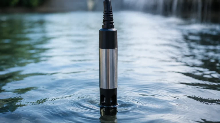
1500-g-l1-s9-oc-x Sensor
1500-g-l1-s9-oc-x Sensor
In the landscape of industrial automation and process control, precision in level measurement is not merely a preference but a fundamental requirement for safety, efficiency, and cost management. The 1500-g-l1-s9-oc-x sensor is a specialized configuration designed to meet the rigorous demands of liquid level monitoring in diverse environments, ranging from municipal water treatment to complex chemical processing. As a component within the broader ecosystem of industrial instrumentation, this sensor type leverages specific physical principles to provide reliable data in real-time.
Understanding the technical nuances of the 1500-g-l1-s9-oc-x sensor requires a deep dive into its measurement mechanics, material composition, and the specific industrial contexts where it excels. This guide serves as a practical engineering reference for selecting, installing, and maintaining this class of sensor within a professional B2B framework.
Measurement Principles: The Foundation of Accuracy
The 1500-g-l1-s9-oc-x sensor typically operates on the principle of hydrostatic pressure measurement. This method is widely regarded in the industry for its robustness and simplicity. The fundamental physics behind this measurement is defined by the relationship between the height of a liquid column and the pressure exerted at its base.
The Hydrostatic Equation
The sensor calculates the level of a liquid based on the formula:
P = ρ × g × h
Where:
* P is the hydrostatic pressure measured by the sensor diaphragm.
* ρ (rho) is the density of the liquid being measured.
* g is the acceleration due to gravity (approximately 9.81 m/s²).
* h is the height of the liquid column above the sensor.
In the 1500-g-l1-s9-oc-x configuration, the "G" designation often signifies "Gauge Pressure." This means the sensor is vented to the atmosphere, allowing it to compensate for changes in barometric pressure automatically. This ensures that the pressure reading reflects only the weight of the liquid, providing an accurate level reading regardless of weather changes or altitude.
Signal Conversion
Once the pressure is detected by the internal sensing element—often a piezoresistive silicon chip or a ceramic thick-film strain gauge—the integrated electronics convert this mechanical stress into a standardized electrical signal. This signal, typically a 4-20mA current loop or a digital RS485 Modbus output, is then transmitted to a PLC (Programmable Logic Controller) or a dedicated level controller for processing and display.
Technical Breakdown of the 1500-g-l1-s9-oc-x Configuration
Industrial part numbers are rarely arbitrary; they are alphanumeric codes that define the physical and electrical characteristics of the device. For the 1500-g-l1-s9-oc-x sensor, the nomenclature points toward specific engineering capabilities:
1. 1500 (Range/Rating): This typically denotes the nominal measurement range. In many systems, this refers to a 1500mm (1.5 meter / 4.92 feet) or a 15-meter (49.2 feet) maximum depth capability, depending on the specific product series scaling.
2. G (Pressure Type): As noted, this indicates Gauge pressure. It is essential for open-tank applications or vented reservoirs where atmospheric pressure must be cancelled out.
3. L1 (Accuracy/Length): This often refers to the accuracy class (e.g., Level 1 precision) or a specific standardized probe length for submersible models.
4. S9 (Material Specification): In the Welk catalog, this designation frequently points to high-grade 316L Stainless Steel construction for the sensor housing and diaphragm, ensuring compatibility with corrosive media.
5. OC (Output Characteristic): This refers to the output configuration, such as an Open Collector switch or a specific current output optimized for long-distance transmission.
For engineers looking to integrate these sensors into larger control architectures, reviewing the full technical documentation on the Main Page is recommended to ensure compatibility with existing hardware.
Practical Selection Table
When evaluating the 1500-g-l1-s9-oc-x sensor against other options in the Welk product line, engineers should consider the following performance parameters:
| Parameter | Specification (Metric) | Specification (Imperial) |
| :— | :— | :— |
| Measurement Range | 0 to 15 m | 0 to 49.2 ft |
| Accuracy (Linearity/Hysteresis) | ±0.25% to ±0.5% FS | ±0.25% to ±0.5% FS |
| Operating Temperature | -20°C to +80°C | -4°F to +176°F |
| Compensated Temperature Range | 0°C to +60°C | 32°F to 140°F |
| Output Signal | 4-20mA / 0-10V / RS485 | 4-20mA / 0-10V / RS485 |
| Housing Material | 316L Stainless Steel | 316L Stainless Steel |
| Ingress Protection | IP68 (Submersible) | NEMA 6P |
| Overload Pressure | 200% Full Scale | 200% Full Scale |
Installation Considerations and Best Practices
Correct installation is as critical as the sensor's internal technology. For the 1500-g-l1-s9-oc-x sensor, particularly in submersible or bottom-mount configurations, several engineering factors must be addressed to ensure long-term reliability.
Positioning and Stability
The sensor should be mounted in a location where the fluid is relatively calm. In tanks with high-speed agitators or significant inflow turbulence, the sensor may experience "noise" in its readings or physical wear on the diaphragm. In such cases, the use of a stilling well—a vertical pipe with vent holes—is highly recommended to isolate the sensor from lateral fluid movement.
Cable Management and Venting
Since this is a gauge pressure sensor ("G" designation), the cable usually contains a small vent tube. This tube allows the internal side of the diaphragm to "breathe" and match the local atmospheric pressure.
* Avoid Kinking: Ensure the cable is not bent at sharp angles, which could pinch the vent tube.
* Moisture Protection: The end of the cable (at the junction box) must be kept dry. Using a desiccant cartridge or a specialized vented junction box prevents moisture from entering the vent tube and causing internal corrosion or sensor drift.
Media Compatibility
While the S9 (316L Stainless Steel) construction offers excellent resistance to many chemicals, it is not universal. Before installation, verify the compatibility of 316L with the specific concentration and temperature of the process fluid. For highly aggressive acids or seawater, alternative coatings or materials like Tantalum or Hastelloy might be required.

Limitations and Common Risks
Every measurement technology has its boundaries. Recognizing where the 1500-g-l1-s9-oc-x sensor might struggle is key to avoiding process downtime.
1. Pressurized Vessels: Because this is a gauge pressure sensor, it cannot be used in sealed, pressurized tanks. In a pressurized environment, the sensor would measure the sum of the liquid head and the gas blanket pressure, leading to a false level reading. For such applications, a differential pressure transmitter is required.
2. Density Fluctuations: Since the sensor measures weight to infer height, any significant change in the liquid's density (due to temperature shifts or changes in chemical concentration) will introduce error. If the density is variable, the control system must be programmed to compensate for these changes.
3. Sediment Accumulation: In wastewater or slurry applications, heavy solids can settle at the bottom of the tank and bury the sensor diaphragm. This can lead to sluggish response times or mechanical damage. Periodic cleaning or mounting the sensor slightly above the floor of the tank can mitigate this risk.
Maintenance and Calibration Procedures
To maintain the Level 1 (L1) accuracy associated with the 1500-g-l1-s9-oc-x sensor, a routine maintenance schedule should be established.
* Visual Inspection: Every 6 to 12 months, the sensor should be inspected for signs of scaling, bio-fouling, or corrosion on the diaphragm.
* Zero-Point Verification: Periodically pull the sensor out of the liquid and check the output. In a dry state, the sensor should output exactly 4.00mA (for a 4-20mA system). Any deviation indicates a "zero drift" that needs to be corrected via the PLC or the sensor's internal calibration trim.
* Span Calibration: For critical applications, a full-scale calibration using a known pressure source or a measured liquid column is recommended annually.
Frequently Asked Questions (FAQ)
Q: Can the 1500-g-l1-s9-oc-x sensor be used in potable water?
A: Yes, provided the housing is cleaned and the cable material (typically PUR or PE) is rated for drinking water contact. The 316L stainless steel construction is generally acceptable for municipal water applications.
Q: What is the maximum cable length for the RS485 version?
A: For digital RS485 Modbus communication, the cable length can extend up to 1,200 meters (approximately 3,937 feet) without significant signal degradation, provided proper shielded twisted-pair cabling is used.
Q: How does the sensor handle freezing temperatures?
A: While the electronics can operate down to -20°C (-4°F), the liquid itself must not freeze. If the liquid freezes around the sensor, the expansion of ice can permanently deform the diaphragm, destroying the sensor's accuracy.
Q: Is the sensor lightning-protected?
A: Most industrial-grade sensors in this series include basic surge protection. However, for outdoor installations in high-lightning areas, additional external surge protectors are recommended to safeguard the control loop.
For further technical assistance or to request a customized quote for specific industrial applications, please refer to the product resources available on the Main Page.