Flow Distributor
Flow Distributor
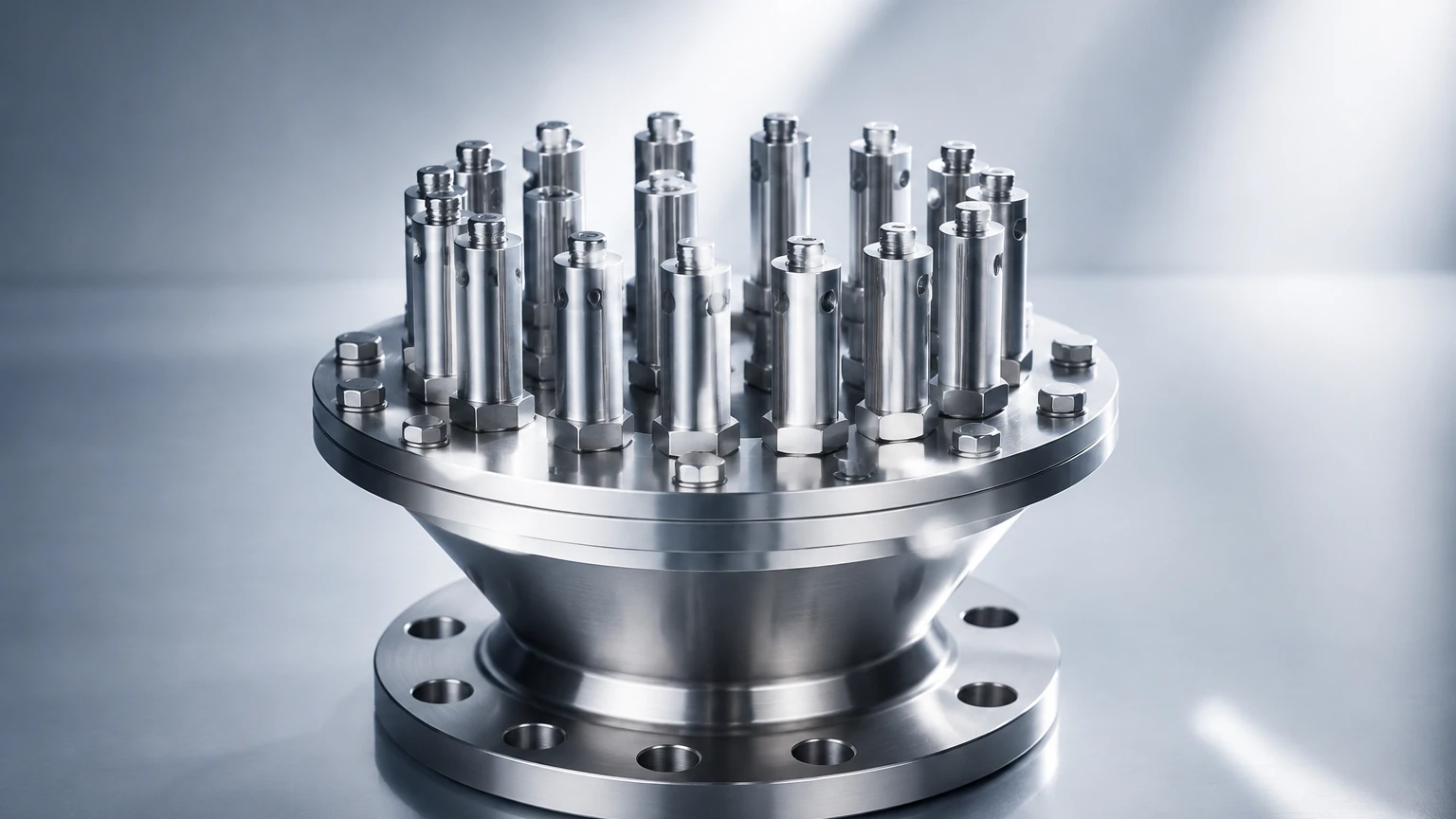
In industrial process engineering, a flow distributor is a critical mechanical component designed to partition a single fluid stream into multiple paths or to spread a fluid evenly across the cross-sectional area of a vessel. Effective flow distribution is essential for the performance of heat exchangers, chemical reactors, distillation columns, and water treatment systems. However, the mechanical efficiency of a flow distributor is rarely an isolated variable; it is deeply dependent on the precise monitoring and control of liquid levels within the system.
For engineers and plant operators, understanding the interaction between a flow distributor and level measurement instrumentation is vital. If the liquid level is too high, the distributor may become submerged, leading to backpressure and improper mixing. If the level is too low, the distributor may "run dry," causing uneven flow patterns and potential damage to downstream equipment. This article examines the technical principles of level measurement in systems utilizing a flow distributor and provides a framework for selecting the appropriate instrumentation.
Core Principles of Level Measurement in Distribution Systems
Before selecting a sensor for a vessel equipped with a flow distributor, it is necessary to understand the physics of the most common measurement technologies. Each method interacts differently with the turbulence and internal geometries created by distribution hardware.
Radar Level Measurement (Non-Contact)
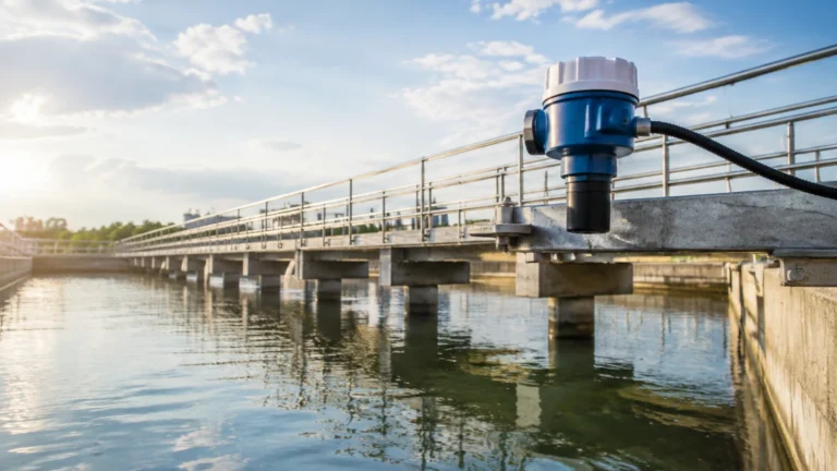
Radar level meters operate on the Time-of-Flight (ToF) principle. The device emits a high-frequency electromagnetic wave (typically in the 26GHz or 80GHz range) toward the liquid surface. The wave reflects off the surface and returns to the sensor. By measuring the time interval between emission and reception, the instrument calculates the distance to the product surface.
In applications involving a flow distributor, radar is often preferred because it is unaffected by changes in pressure, temperature, or vapor space composition. High-frequency 80GHz radar is particularly effective because it offers a narrow beam angle, allowing the signal to bypass internal distributor piping and focus strictly on the liquid surface.
Ultrasonic Level Sensing
Ultrasonic sensors also use the ToF principle but utilize sound waves instead of electromagnetic waves. A transducer emits an ultrasonic pulse that bounces off the liquid surface. Because sound requires a medium to travel through, these sensors are sensitive to air temperature fluctuations and heavy foam. In systems where a flow distributor creates significant surface agitation or foam, ultrasonic technology may require careful calibration or the use of a stilling well to ensure accuracy.
Hydrostatic Pressure Measurement
Hydrostatic transmitters measure the level by sensing the pressure exerted by the liquid column. The relationship is defined by the formula: $P = \rho \times g \times h$, where $P$ is pressure, $\rho$ is the fluid density, $g$ is gravity, and $h$ is the height of the liquid. This method is highly reliable in vessels where the surface is extremely turbulent due to the action of a flow distributor, as the pressure at the bottom of the tank remains relatively stable regardless of surface ripples.
Magnetic Level Gauges
Magnetic level gauges provide a visual indication and can be equipped with transmitters for remote monitoring. They consist of a bypass chamber connected to the vessel. A float containing a magnet moves with the liquid level, flipping magnetic flags on an external scale. Because the measurement occurs in a separate chamber, it is entirely isolated from the turbulence generated by the flow distributor inside the main tank.
The Relationship Between Flow Distribution and Level Control
A flow distributor relies on a specific "head" or pressure to function correctly. In gravity-fed distributors, such as those found in large-scale cooling towers or wastewater clarifiers, the liquid level determines the velocity at which the fluid exits the distributor orifices.
1. Uniformity of Distribution: If the level is inconsistent, the flow distributor may provide more fluid to one side of a packed bed than the other, leading to "channeling." This reduces the efficiency of chemical reactions or thermal exchange.
2. Prevention of Aeration: In many chemical processes, it is important to prevent the flow distributor from splashing fluid from a great height, which can introduce unwanted air or gas into the liquid. Level sensors ensure the distance between the distributor and the surface is maintained within an optimal range.
3. System Safety: In high-pressure vessels, the flow distributor is often part of a delicate balance. Level switches act as a secondary safety layer to prevent overflow into gas outlet lines or dry-running of pumps.
For a comprehensive overview of how these instruments integrate into broader industrial automation frameworks, engineers can consult the Main Page for detailed technical specifications and application-specific data sheets.
Selection Criteria for Level Instruments Near Flow Distributors
Choosing the right sensor requires an evaluation of the physical environment and the fluid properties. The following table provides a comparison of technologies in the context of flow distribution systems.
| Technology | Accuracy | Turbulence Resistance | Suitability for Narrow Tanks | Maintenance Needs |
| :— | :— | :— | :— | :— |
| 80GHz Radar | High (±1mm) | Excellent | Excellent | Low (Non-contact) |
| Ultrasonic | Moderate | Fair | Poor (Wide beam) | Moderate |
| Hydrostatic | High | Excellent | Good | Moderate (Wetted) |
| Magnetic Gauge | High | Excellent | Good (External) | Low |
| Level Switch | N/A (Point) | Good | Good | Low |
Practical Selection Steps
1. Identify Internal Obstructions: Map the location of the flow distributor, spray nozzles, and support beams. Ensure the sensor's signal path (beam angle) does not intersect with these components.
2. Assess Surface Conditions: If the flow distributor creates heavy foam, avoid standard ultrasonic sensors. Opt for radar or hydrostatic transmitters.
3. Determine Process Conditions: For temperatures exceeding 150°C (302°F) or pressures above 40 bar (580 psi), specialized radar or magnetic level gauges are required.
Installation Considerations and Best Practices
Proper installation is the most significant factor in the reliability of level measurement near a flow distributor. Even the most advanced sensor will fail if it is positioned directly in the path of an incoming fluid stream.
Avoiding the Input Stream
The level sensor should never be installed directly above or below the flow distributor's primary discharge point. The force of the moving fluid can cause false echoes in radar/ultrasonic units or mechanical fatigue in float-based systems. A minimum distance of 500mm (approximately 20 inches) from the flow stream is generally recommended.
The Use of Stilling Wells
In vessels where the flow distributor causes extreme surface turbulence, a stilling well (or bypass pipe) should be used. A stilling well is a vertical pipe installed inside the tank that acts as a dampener. The liquid level inside the pipe remains the same as the tank level but without the waves and foam. Radar and ultrasonic sensors can then measure the level inside the pipe with high precision.
Mounting Nozzles
When using top-mounted sensors like radar, the mounting nozzle height should be kept as short as possible. If the nozzle is too long, it can create internal reflections (ringing) that interfere with the signal, especially if the flow distributor is located close to the top of the tank.
Limitations and Potential Risks
While modern instrumentation is robust, there are specific limitations to consider in flow distribution applications:
* Build-up and Scaling: In industries like wastewater or mining, the flow distributor may spray fluids that cause mineral build-up on the sensor face. Non-contact sensors with PTFE or PFA coatings are recommended to mitigate this.
* Vapor and Condensation: If the process involves hot liquids, condensation can form on the sensor lens. Some radar units feature a "drip-off" antenna design that allows condensation to run off without affecting the signal.
* Minimum Measuring Distance: All top-down sensors have a "dead zone" or "blocking distance" (typically 10cm to 50cm / 4 to 20 inches). If the flow distributor is mounted very high in the tank, the liquid level must be controlled so it does not enter this dead zone.
Frequently Asked Questions (FAQ)
Q: Can I use a level sensor to detect if the flow distributor is clogged?
A: Indirectly, yes. If the level in the supply header rises while the level in the main vessel remains low or drops, it often indicates a restriction or clog in the flow distributor orifices.
Q: How does the beam angle of a radar sensor affect its placement near a distributor?
A: A wider beam angle (e.g., 10°) is more likely to hit the edges of a flow distributor or internal baffles, causing interference. A narrow beam angle (e.g., 3° to 4°), common in 80GHz radar, allows for installation in tighter spaces.
Q: Are hydrostatic sensors affected by the velocity of the fluid from the distributor?
A: Yes, if the sensor is placed directly in a high-velocity flow path, the "Bernoulli effect" can cause a pressure drop, leading to an inaccurate level reading. Sensors should be placed in a "quiet" zone of the tank.
Q: What maintenance is required for level sensors in these systems?
A: Non-contact sensors require periodic inspection for material build-up. Wetted sensors, like hydrostatic or magnetic floats, may require cleaning or recalibration depending on the corrosivity and cleanliness of the fluid.
For further technical guidance on selecting the right instrument for your specific flow distributor configuration, please visit the Main Page for expert support and product documentation.