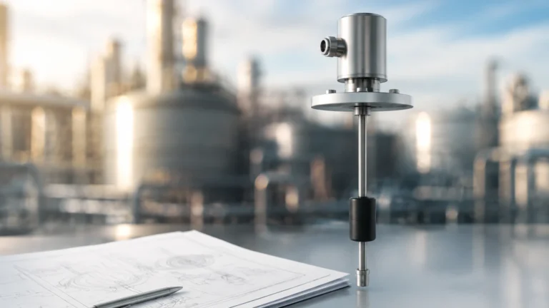
4-20 Ma Intrinsically Safe Hazardous Areas
4-20 Ma Intrinsically Safe Hazardous Areas
In industrial process control, the measurement of liquid and solid levels often occurs in environments where explosive gases, vapors, or dusts are present. To ensure safety in these volatile settings, engineers utilize specific protection methods. Among the most prevalent is the use of 4-20 ma intrinsically safe hazardous areas protocols. This approach focuses on limiting the electrical and thermal energy available to a level measurement instrument to a point where it cannot ignite a specific hazardous atmospheric mixture.
Understanding the integration of 4-20 mA current loops within intrinsically safe (IS) frameworks is essential for maintaining plant safety while achieving precise data transmission over long distances. This guide examines the principles, selection criteria, and installation requirements for level instruments operating in these demanding conditions.
Principles of 4-20 mA Loops and Intrinsic Safety
The 4-20 mA current loop is the global standard for transmitting sensor information in industrial automation. In this system, a 4 mA signal represents the lower range value (0%), and a 20 mA signal represents the upper range value (100%). This "live zero" at 4 mA allows the system to distinguish between a zero-level reading and a broken wire or instrument failure.
The Concept of Intrinsic Safety (IS)
Intrinsic Safety is a protection technique based on the limitation of electrical energy (voltage and current) and stored energy (capacitance and inductance) within a circuit. Unlike "explosion-proof" methods that seek to contain an internal explosion within a heavy-duty enclosure, Intrinsic Safety prevents the explosion from occurring in the first place.
In 4-20 ma intrinsically safe hazardous areas, the system is designed so that even under fault conditions—such as a short circuit or a broken cable—the spark or thermal effect produced is insufficient to ignite the surrounding explosive atmosphere. This makes IS the preferred method for Zone 0 and Zone 1 environments where hazardous substances are frequently or continuously present.
The Role of the Associated Apparatus
A complete intrinsically safe 4-20 mA loop consists of three primary components:
1. The Field Device: An intrinsically safe level transmitter (e.g., a radar or hydrostatic sensor) located in the hazardous area.
2. The Interconnecting Wiring: Specifically rated cables that connect the field device to the control room.
3. The Associated Apparatus: Usually a Zener barrier or a galvanic isolator located in a safe area. This component limits the energy flowing from the control system into the hazardous area.
Hazardous Area Classifications
Before selecting a level meter, it is necessary to understand the classification of the area where the 4-20 mA loop will be installed. Most international standards (IECEx/ATEX) categorize hazardous areas into Zones based on the frequency and duration of the occurrence of an explosive atmosphere.
* Zone 0: An area in which an explosive atmosphere is present continuously or for long periods (e.g., inside a fuel storage tank).
* Zone 1: An area in which an explosive atmosphere is likely to occur in normal operation (e.g., near a loading rack).
* Zone 2: An area in which an explosive atmosphere is not likely to occur in normal operation, and if it does, it will exist for a short period only.
For North American standards (NEC), these are often categorized into Division 1 (encompassing Zones 0 and 1) and Division 2 (equivalent to Zone 2).
Selection Criteria for Level Instruments in IS Areas
When choosing a level measurement solution for 4-20 ma intrinsically safe hazardous areas, several technical factors must be evaluated to ensure both functional accuracy and regulatory compliance. For more detailed technical specifications, engineers may Review product options and application support to match specific site requirements.
1. Certification and Marking
Instruments must carry the appropriate certification for the specific gas or dust group present. Common markings include:
* Ex ia: Suitable for Zone 0 (highest safety level, remains safe with two independent faults).
* Ex ib: Suitable for Zone 1 (remains safe with one fault).
* Ex ic: Suitable for Zone 2.
2. Entity Parameters
To ensure the loop is safe, the "Entity Parameters" of the field device must be matched with the safety barrier. These include:
* Ui (Maximum Input Voltage): The maximum voltage that can be applied to the device.
* Ii (Maximum Input Current): The maximum current that can be applied.
* Pi (Maximum Input Power): The maximum power the device can dissipate.
* Ci and Li (Internal Capacitance and Inductance): The energy stored within the device itself.
3. Measurement Technology Suitability
Different level measurement technologies offer various advantages depending on the medium and the hazardous zone.
| Technology | Typical IS Rating | Best Use Case | Limitations |
| :— | :— | :— | :— |
| Radar (GWR/Non-Contact) | Ex ia (Zone 0) | Chemical tanks, volatile liquids | High initial cost |
| Ultrasonic | Ex ia / Ex ib | Water treatment, open channels | Affected by foam and heavy vapors |
| Hydrostatic | Ex ia | Deep wells, vented tanks | Requires chemical compatibility with sensor diaphragm |
| Magnetic Level Gauge | Simple Apparatus | High-pressure boilers, toxic fluids | Requires bypass piping |
| Level Switches | Ex ia | High/Low alarm protection | Point measurement only |
Practical Installation Considerations
Installing a 4-20 mA loop in a hazardous area requires strict adherence to engineering standards to prevent compromising the safety integrity of the system.
Cable Routing and Separation
Intrinsically safe wiring must be physically separated from non-intrinsically safe wiring. This is typically achieved by using separate conduits or by maintaining a minimum distance of 50 mm (approx. 2 inches) between the cable types. IS cables are often color-coded blue for easy identification.
Grounding and Earthing
In a system using Zener barriers, a high-integrity "IS Earth" is required. This ground must have a resistance of less than 1 Ohm to ensure that fault currents are safely diverted away from the hazardous area. If galvanic isolators are used, this specific grounding requirement is often relaxed, as the isolator provides electrical separation between the input and output circuits.
Cable Parameters
The capacitance (Cc) and inductance (Lc) of the interconnecting cable must be added to the field device's parameters. If the total capacitance (Ci + Cc) exceeds the limit allowed by the safety barrier, the system is no longer considered intrinsically safe.

Limitations of 4-20 mA IS Systems
While highly effective, 4-20 ma intrinsically safe hazardous areas designs have inherent limitations:
* Power Constraints: Because the energy is strictly limited, some high-power devices (such as heated sensors or complex displays) may not be able to operate on an IS loop.
* Distance vs. Resistance: The safety barrier adds resistance to the loop. If the cable is too long or the barrier resistance is too high, the 24V DC supply may not be sufficient to drive the 20 mA signal through the entire circuit.
* Maintenance Complexity: Any replacement part or modification must be verified against the original safety documentation to ensure the IS rating is maintained.
Frequently Asked Questions
Q: Can I use a standard 4-20 mA transmitter in a hazardous area if I use a barrier?
No. The field device itself must be certified as "Intrinsically Safe." Using a barrier with a non-IS device does not guarantee safety, as the non-IS device may have internal components that store enough energy to cause ignition.
Q: What is the difference between a Zener Barrier and a Galvanic Isolator?
A Zener barrier uses diodes to shunt excess voltage to ground, requiring a dedicated IS earth. A galvanic isolator uses transformers or optical isolators to provide electrical separation, eliminating the need for a dedicated IS earth and providing better protection against ground loops.
Q: How do I calculate the maximum cable length for an IS loop?
You must calculate the total loop resistance (including the barrier, cable, and transmitter) and ensure the power supply can maintain at least 12V (or the transmitter's minimum requirement) at 20 mA. Additionally, you must ensure the total cable capacitance and inductance do not exceed the barrier's maximum allowed values.
Q: Is 4-20 mA better than digital protocols like HART in hazardous areas?
Many IS level transmitters use 4-20 mA with HART protocol superimposed. This allows for digital configuration and diagnostics while maintaining the safety and simplicity of the 4-20 mA analog loop.
Summary and Next Steps
Implementing 4-20 ma intrinsically safe hazardous areas solutions is a critical task for process engineers in the chemical, oil and gas, and water treatment industries. By limiting energy and adhering to strict installation standards, these systems provide a reliable and safe method for monitoring critical levels in explosive environments.
When planning a level measurement project, always verify the hazardous zone classification and confirm the compatibility of the field device, cable, and safety barrier. For comprehensive technical data and a wide range of certified instruments, professionals should visit the Main Page to explore specific hardware solutions tailored to industrial automation and safety compliance.
Download 4-20 Ma Intrinsically Safe Hazardous Areas as a PDF