Aa5022
Aa5022
In the modern industrial landscape, the accuracy of level measurement is a cornerstone of operational efficiency, safety, and regulatory compliance. The Aa5022 series, developed by Welk, represents a sophisticated advancement in level sensing technology, designed to address the complexities of liquid and solid storage across various sectors. Whether managing volatile chemicals, wastewater, or bulk solids, the Aa5022 provides a reliable data stream essential for automated process control.
This technical guide explores the engineering principles, selection variables, and installation protocols for the Aa5022. By understanding the underlying physics and the environmental factors that influence sensor performance, engineers can optimize their level measurement strategies and ensure long-term system stability.
Fundamental Measurement Principles of the Aa5022 Series
Before implementing the Aa5022, it is critical to understand the specific measurement technologies employed within the series. Level measurement instruments generally utilize either mechanical contact or non-contact wave propagation. The Aa5022 series specializes in non-contact technologies, primarily Radar (Microwave) and Ultrasonic sensing.
Ultrasonic Level Sensing
Ultrasonic variants of the Aa5022 utilize a piezoelectric crystal to emit high-frequency sound pulses. These pulses travel through the air or vapor space, reflect off the surface of the medium, and return to the transducer. The device measures the time elapsed between emission and reception.
One critical consideration for ultrasonic sensors is the speed of sound. Sound velocity is highly dependent on air temperature. To maintain accuracy, the Aa5022 incorporates an integrated temperature sensor to compensate for these fluctuations. However, because sound requires a medium to travel, ultrasonic sensors cannot be used in vacuum applications or in environments where heavy foam or high-pressure steam significantly attenuates the acoustic signal.
Radar (Microwave) Technology
For more demanding environments, the Aa5022 radar units utilize electromagnetic waves. These waves travel at the speed of light and are largely unaffected by temperature, pressure, or vacuum conditions.
1. Pulse Radar: This method sends short microwave bursts and measures the transit time. It is energy-efficient and suitable for many standard applications.
2. FMCW (Frequency Modulated Continuous Wave): Advanced Aa5022 models often use FMCW. Instead of pulses, the sensor transmits a continuous signal with a varying frequency. The distance is calculated by comparing the frequency of the reflected signal with the frequency currently being transmitted. FMCW offers superior resolution and accuracy, especially in tanks with internal obstructions or turbulent surfaces.
Critical Selection Criteria for Industrial Applications
Selecting the appropriate Aa5022 configuration requires a detailed analysis of the process medium and the vessel environment. The following factors are primary determinants in instrument specification.
Dielectric Constant (εr)
For radar-based Aa5022 units, the dielectric constant of the medium determines how much energy is reflected back to the sensor. Water has a high dielectric constant (εr ≈ 80) and provides a strong reflection. Conversely, hydrocarbons like oils and solvents have low dielectric constants (εr < 2.5), which absorb more energy and reflect less. In such cases, a high-sensitivity Aa5022 with a larger antenna or a guided wave radar (GWR) configuration may be required.
Process Temperature and Pressure
Standard Aa5022 units are typically rated for temperatures up to 80°C (176°F). However, in chemical reactors or steam-jacketed vessels, temperatures can exceed 250°C (482°F). High-temperature variants utilize specialized cooling fins or ceramic seals to protect the electronics from thermal damage. Similarly, pressure ratings must be matched to the vessel; while ultrasonic units are generally limited to 3 bar (43.5 psi), radar units can withstand up to 40 bar (580 psi) or higher.
Selection Matrix for Aa5022 Models
| Application Parameter | Aa5022-U (Ultrasonic) | Aa5022-R (Radar) | Aa5022-HT (High Temp) |
| :— | :— | :— | :— |
| Max Range | 15 m (49 ft) | 30 m (98 ft) | 20 m (65 ft) |
| Accuracy | ±0.25% of range | ±2 mm (0.07 in) | ±3 mm (0.11 in) |
| Process Temp. | -40 to 80°C | -40 to 150°C | -40 to 250°C |
| Pressure Limit | 3 bar | 40 bar | 40 bar |
| Best Use Case | Open channels, water tanks | Chemical storage, oils | Reactors, boilers |
| Key Limitation | Foam, Vacuum | Low dielectric liquids | Cost-intensive |
For engineers looking to compare specific model numbers and technical data sheets, the Main Page provides a comprehensive digital repository of Welk’s current product offerings and application support documentation.
Engineering Design and Installation Best Practices
The reliability of the Aa5022 is often determined during the installation phase. Improper mounting can lead to signal loss or false readings caused by internal vessel structures.
Nozzle Geometry and Placement
The Aa5022 is typically mounted on a nozzle at the top of the tank. The height and diameter of this nozzle are critical. If the nozzle is too narrow or too long, the signal may reflect off the nozzle walls before reaching the medium. For optimal performance, the sensor face should extend slightly below the nozzle opening. If this is not possible, the nozzle's internal surface must be smooth and free of burrs or welding seams.
Beam Angle and Obstruction Management
Every Aa5022 sensor has a specific beam angle (e.g., 8° or 12°). The beam expands as it travels downward. Engineers must ensure that the "beam footprint" does not intersect with internal obstructions such as:
* Agitators and Impellers: Moving parts can create intermittent false echoes.
* Heating Coils: Static structures that reflect signals.
* Inflow Streams: Material falling directly into the path of the beam will cause erratic readings.
Use of Stilling Wells and Bypass Chambers
In applications involving heavy turbulence, boiling surfaces, or thick foam, the Aa5022 can be installed inside a stilling well or an external bypass chamber. These structures act as a calm environment for the sensor, isolating the measurement from surface disturbances. When using a stilling well, the Aa5022 must be configured to account for the pipe's internal diameter to avoid interference from the pipe walls.
Digital Communication and Integration into Process Control
In the era of Industry 4.0, the Aa5022 is more than a simple sensor; it is a data node. Modern industrial automation requires seamless integration between field instruments and control systems like PLCs, DCS, or SCADA.
4-20mA and HART Protocol
The standard output for the Aa5022 is a 4-20mA analog signal, where 4mA represents the empty tank and 20mA represents the full tank. Most units also include HART (Highway Addressable Remote Transducer) protocol. HART superimposes a digital signal over the analog loop, allowing for remote configuration, diagnostics, and multi-variable reporting (such as temperature and signal strength) without additional wiring.
RS485 and Modbus RTU
For large-scale facilities where multiple Aa5022 units are deployed, RS485 Modbus RTU is often preferred. This digital bus system allows for daisy-chaining multiple sensors on a single pair of wires, significantly reducing installation costs. It also provides high-speed data transfer and robust immunity to electromagnetic interference (EMI) commonly found in industrial environments.
Smart Diagnostics and Echo Mapping
The Aa5022 features advanced signal processing software. During commissioning, technicians can perform "echo mapping." This process records all static reflections (from ladders or nozzles) in an empty tank and stores them in the sensor's memory. The sensor then ignores these static echoes during operation, focusing only on the moving echo from the material surface. This significantly increases the reliability of the measurement in complex tank geometries.
Industry-Specific Application Case Studies
The versatility of the Aa5022 is best demonstrated through its performance in diverse industrial environments.
Water and Wastewater Treatment
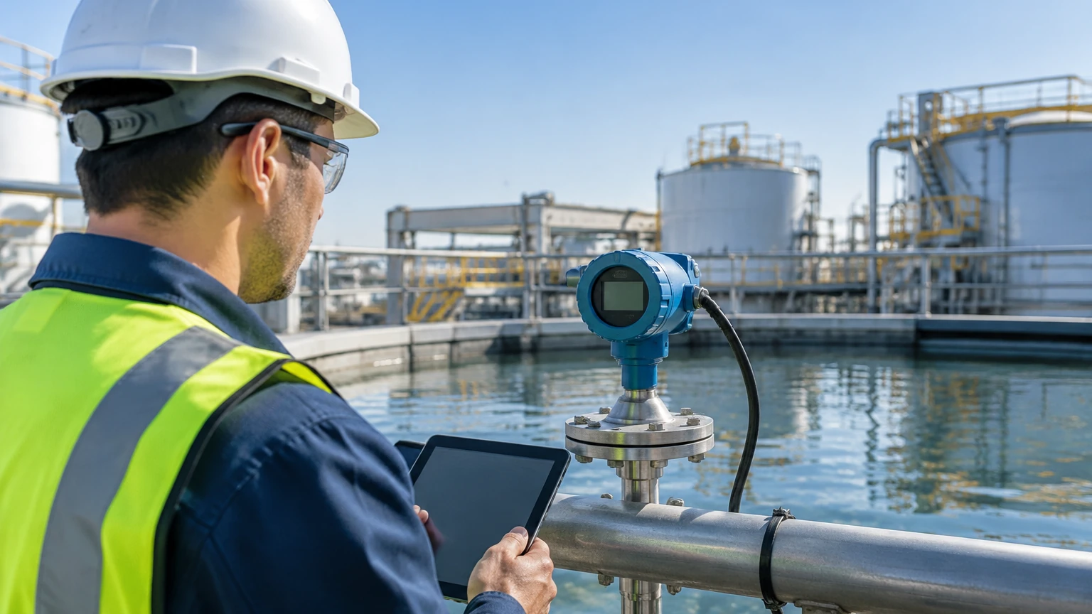
In municipal water treatment, the Aa5022 is frequently used for open channel flow measurement and sump level control. Ultrasonic versions are favored here for their cost-effectiveness and resistance to the humid, corrosive atmospheres found in sewers. The non-contact nature of the Aa5022 ensures that the sensor does not become fouled by debris or biological growth.
Chemical Processing
Chemical plants often deal with aggressive acids and bases. The Aa5022-Corrosive model utilizes PTFE (Teflon) or PVDF wetted parts to ensure chemical compatibility. In these applications, radar is often the preferred technology because it can measure accurately through plastic tank walls or through heavy vapors that would baffle an ultrasonic sensor.
Oil and Gas Storage
In the oil and gas industry, accuracy is essential for inventory management and custody transfer. The Aa5022 radar units provide the high precision required to calculate volumes in large storage tanks. Because these environments are often classified as hazardous (explosive), the Aa5022 is available with Ex-proof (Explosion-proof) or Intrinsically Safe (IS) certifications to meet global safety standards.
Maintenance, Troubleshooting, and Lifecycle Management
While the Aa5022 is designed for low maintenance, a proactive approach to lifecycle management ensures the highest uptime.
Routine Maintenance Checklist
1. Sensor Face Inspection: Periodically check for material buildup or condensation on the transducer face. While many Aa5022 units have a self-cleaning effect due to vibration or materials like PTFE, heavy buildup can attenuate the signal.
2. Cable Integrity: Inspect cable glands and conduits for signs of moisture ingress or physical damage, especially in outdoor installations.
3. Verification: Compare the Aa5022 reading against a manual reference (such as a dip tape) at least once a year to ensure there is no calibration drift.
Troubleshooting Common Issues
Issue: Loss of Echo (LOE)
* Cause: This usually occurs when the reflected signal is too weak to be detected. This can be caused by heavy foam, extreme turbulence, or the material level falling into the "dead zone."
* Solution: Check the mounting height and consider using a stilling well or a higher-power radar antenna.
Issue: Fluctuating Readings
* Cause: Often caused by an agitator blade passing through the beam or heavy surface turbulence.
* Solution: Increase the damping (integration time) in the sensor settings or use the echo mapping function to mask the agitator interference.
Issue: Constant Full or Empty Reading
* Cause: This may indicate a hardware failure or a significant obstruction reflecting the signal right at the sensor face.
* Solution: Perform a factory reset and re-map the tank. If the problem persists, check the power supply voltage to ensure it meets the minimum requirements for the 4-20mA loop.
Conclusion
The Aa5022 series represents a robust solution for the complex challenges of industrial level measurement. By combining advanced wave physics with user-friendly digital integration, Welk provides a tool that enhances both process safety and economic efficiency. Successful implementation requires a holistic approach—from the initial assessment of the medium's dielectric properties to the precision of the physical installation and the configuration of digital signal processing.
As process requirements evolve and the demand for data-driven decision-making grows, instruments like the Aa5022 will continue to play a vital role in the industrial ecosystem. For detailed technical support, custom OEM/ODM inquiries, or to review the full range of level measurement instruments, professionals are encouraged to visit the Main Page for expert guidance and product specifications.