Analog vs Digital Sensors
Analog vs Digital Sensors
In the realm of industrial automation and process control, the choice between analog and digital sensors is a fundamental decision that influences system architecture, accuracy, and long-term maintenance costs. Whether monitoring the level of caustic chemicals in a storage tank or measuring water levels in a municipal treatment plant, understanding the nuances of signal transmission is critical for engineering success. Welk, as a professional manufacturer of industrial level measurement instruments, provides a wide array of solutions including radar level meters and ultrasonic sensors that utilize both signal types to meet diverse application requirements.
Fundamental Measurement Principles: Analog vs Digital
To effectively compare analog vs digital sensors, one must first understand how these devices translate physical phenomena—such as the height of a liquid—into electrical information that a Programmable Logic Controller (PLC) or Distributed Control System (DCS) can interpret.
Analog Measurement Principles
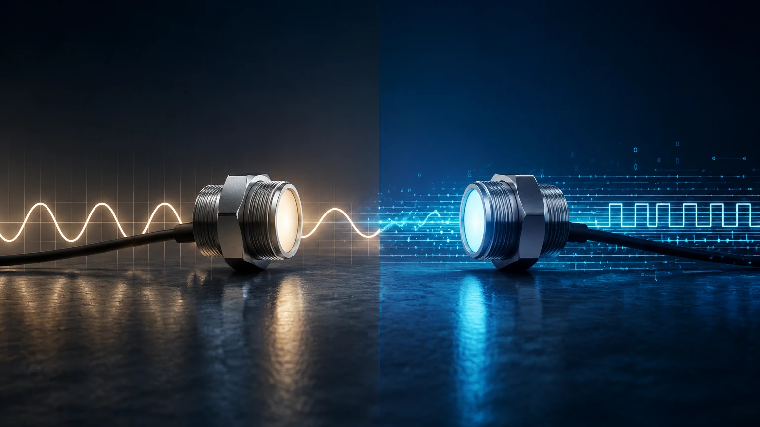
Analog sensors represent physical variables as a continuous electrical signal. In level measurement, an analog sensor (like a hydrostatic transmitter) generates a voltage or current that is directly proportional to the level of the medium. For example, in a 0 to 10-meter (approx. 32.8 ft) tank, a 4-20mA output would provide 4mA when the tank is empty, 12mA when it is half full, and 20mA when it is at maximum capacity. Because the signal is continuous, it can theoretically represent an infinite number of values within its range, limited only by the resolution of the receiving equipment.
Digital Measurement Principles
Digital sensors, conversely, convert the physical measurement into a discrete, numerical value within the sensor itself before transmission. This data is sent as a series of binary bits (0s and 1s) using specific communication protocols. Instead of a varying current, a digital radar level meter sends a data packet containing the exact measurement (e.g., "5.432 meters"). This process involves an internal Analog-to-Digital Converter (ADC) and a microprocessor. Digital communication is often bi-directional, allowing the controller to not only receive level data but also send configuration commands or request diagnostic status from the sensor.
Key Characteristics of Analog Level Sensors
Analog sensors have been the backbone of industrial processing for decades. Their simplicity and standardized nature make them a reliable choice for many straightforward applications.
* Standardized Interfaces: The most common analog signal is the 4-20mA current loop. Unlike voltage signals (0-10V), current loops are less susceptible to signal degradation over long cable runs because the current remains constant regardless of wire resistance (up to the limit of the power supply).
* Real-time Response: Analog signals provide an instantaneous representation of the process variable. There is no "sampling delay" or processing overhead associated with packetizing data, which can be beneficial in high-speed control loops.
* Ease of Troubleshooting: A technician with a basic multimeter can verify an analog sensor's operation by measuring the current in the loop. If the meter reads 12mA, the system is functioning at 50% scale.
However, analog sensors are inherently limited by their inability to transmit anything beyond the primary process variable. They cannot communicate internal temperatures, signal strength, or hardware faults without additional wiring or complex signaling tricks.
Key Characteristics of Digital Level Sensors
Digital sensors represent the evolution of industrial instrumentation, offering "smart" capabilities that go far beyond basic level measurement.
* Enhanced Data Integrity: Digital signals are significantly more robust against Electromagnetic Interference (EMI). Since the data is transmitted as discrete pulses, small amounts of electrical noise do not change the numerical value being sent. If a bit is corrupted, error-checking protocols (like parity bits or CRC) can identify the issue.
* Multi-Variable Transmission: A single digital connection (such as Modbus RTU or Profibus) can transmit multiple data points simultaneously. A digital ultrasonic level sensor can report the distance to the liquid, the ambient temperature (for sound speed compensation), the signal echo strength, and any error codes over a single pair of wires.
* Remote Configuration and Diagnostics: Digital sensors allow engineers to adjust parameters—such as blanking distances or sensitivity—remotely from the control room. This reduces the need for technicians to climb tanks or enter hazardous areas for routine adjustments.
Comparative Analysis: Analog vs Digital Sensors
When selecting a level measurement solution, engineers must weigh the technical trade-offs. The following table provides a direct comparison of the two technologies across key performance indicators.
| Feature | Analog Sensors (4-20mA) | Digital Sensors (Modbus, HART, etc.) |
| :— | :— | :— |
| Signal Type | Continuous electrical current/voltage | Discrete binary data packets |
| Noise Immunity | Susceptible to EMI/RFI interference | High resistance to electrical noise |
| Data Capacity | Single variable only | Multiple variables + diagnostics |
| Wiring Complexity | 1 pair per sensor (Point-to-Point) | Multiple sensors on 1 pair (Bus topology) |
| Calibration | Requires manual zero/span adjustment | Often self-calibrating or remote digital setup |
| Distance | Limited by loop resistance (~1000m) | Can extend kilometers with repeaters |
| System Cost | Lower initial sensor cost | Higher sensor cost, lower wiring cost |
Practical Application and Selection Criteria
The decision between analog vs digital sensors often depends on the existing infrastructure and the complexity of the process. For more detailed product specifications and technology comparisons, you can visit the Main Page of Welk's industrial catalog.
When to Choose Analog
Analog sensors remain the preferred choice for legacy systems where the PLC only supports analog input cards. They are also ideal for simple, localized tasks where advanced diagnostics are unnecessary. In environments with very low electrical noise and short cable runs, the cost-effectiveness of an analog 4-20mA sensor is difficult to beat.
When to Choose Digital
Digital sensors are the standard for modern "Industry 4.0" facilities. They are essential when high precision is required over long distances or when the sensor is located in a hard-to-reach area where remote diagnostics can save hours of maintenance time. Furthermore, if you need to network dozens of sensors, a digital bus system (like RS-485) significantly reduces the amount of copper cabling required, as multiple sensors can share the same communication line.
Installation and Maintenance Considerations
Successful deployment of any level sensor requires strict adherence to installation best practices, which differ significantly between analog and digital formats.
Analog Installation:
1. Shielding: Always use shielded twisted-pair (STP) cabling to minimize noise pickup. The shield should be grounded at one end only (usually the control cabinet) to prevent ground loops.
2. Voltage Drop: Ensure the power supply can overcome the total resistance of the wire and the sensor's internal load. For a 24VDC system, long runs of thin-gauge wire can cause the voltage at the sensor to drop below the required operating threshold.
Digital Installation:
1. Termination: For bus systems like Modbus or Profibus, proper termination resistors (typically 120 ohms) must be placed at the beginning and end of the bus to prevent signal reflections.
2. Addressing: Each digital sensor on a network must have a unique address. Conflicting addresses will cause communication failures that can be difficult to diagnose.
3. Update Rates: While digital is accurate, the "polling rate" (how often the PLC asks for data) must be configured correctly to ensure the control system reacts quickly enough to rapid level changes.
Limitations and Challenges
Neither technology is without its drawbacks. Analog sensors suffer from "quantization loss" when the signal is finally converted by the PLC's input card; if a 12-bit PLC card is used, the continuous analog signal is chopped into 4,096 steps, potentially losing fine detail. Analog signals also degrade over time as components age, requiring periodic re-calibration of zero and span settings.
Digital sensors, while robust, introduce a layer of software complexity. Protocol incompatibility is a common challenge; a "Modbus" sensor from one manufacturer may use different data registers than one from another, requiring custom programming. Additionally, digital sensors generally have a higher power consumption due to the onboard processing electronics, which can be a factor in solar-powered or battery-operated remote sites.
Frequently Asked Questions (FAQs)
Q: Can I use a digital sensor with an analog PLC?
A: Many modern digital sensors, such as those equipped with HART (Highway Addressable Remote Transducer) protocol, are hybrid. They provide a standard 4-20mA analog signal for the primary variable while overlaying a digital signal on the same wires for diagnostics. This allows for a gradual transition from analog to digital systems.
Q: Which is better for hazardous areas (Ex-zones)?
A: Both are available in intrinsically safe and explosion-proof versions. However, analog 4-20mA loops are often easier to design for intrinsic safety because the power levels are consistently low and well-defined.
Q: Does digital always mean more accurate?
A: Not necessarily. The accuracy depends on the sensing element (e.g., the radar frequency or the quality of the pressure diaphragm). However, digital transmission ensures that the accuracy of the sensing element is preserved all the way to the controller without being degraded by electrical noise or wire resistance.
Conclusion
In the debate of analog vs digital sensors, the "best" choice is defined by the specific needs of the industrial environment. Analog sensors offer simplicity, real-time response, and ease of use for basic applications. Digital sensors provide the data depth, noise immunity, and networking capabilities required for sophisticated, modern automation. By understanding these principles and limitations, engineers can select the most reliable level measurement instruments for their unique process requirements. For professionals seeking high-quality level measurement hardware tailored to these standards, exploring the comprehensive range of radar, ultrasonic, and hydrostatic sensors is the next logical step in optimizing process efficiency.