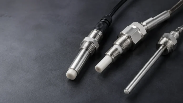
Ultrasonic Depth Sensor
Ultrasonic Depth Sensor
In the field of industrial automation and process control, the ability to monitor liquid levels and solid heights accurately without physical contact is a significant advantage. The ultrasonic depth sensor has emerged as a cornerstone technology for these applications, providing a reliable, cost-effective, and low-maintenance solution for diverse industries ranging from water treatment to chemical processing. As a professional manufacturer, Welk specializes in these high-precision instruments, ensuring they meet the rigorous demands of modern engineering.
Selecting the right ultrasonic depth sensor requires a thorough understanding of acoustic physics, environmental variables, and the specific geometric constraints of the vessel or channel being measured. This guide provides a comprehensive technical overview of ultrasonic technology, selection criteria, and practical installation strategies for engineering professionals.
Measurement Principles of Ultrasonic Technology
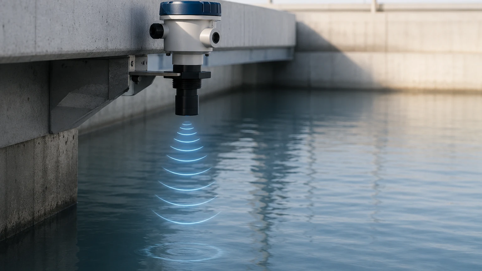
An ultrasonic depth sensor operates on the "Time of Flight" (ToF) principle. The device contains a piezoelectric transducer that acts as both a transmitter and a receiver.
The Acoustic Pulse
The sensor emits a burst of high-frequency sound waves—typically between 20 kHz and 200 kHz—directed toward the target surface. These waves travel through the air at the speed of sound. When the pulse hits the surface of the medium (liquid or solid), a portion of the energy is reflected back toward the sensor as an echo.
Distance Calculation
The internal microprocessor measures the precise time interval between the emission of the pulse and the reception of the echo. The distance ($D$) from the sensor to the surface is calculated using the following formula:
$D = (c \times t) / 2$
Where:
* c is the speed of sound in the medium (usually air).
* t is the total elapsed time for the round trip.
The depth of the material in a tank is then determined by subtracting this measured distance from the known total height of the vessel.
Temperature Compensation
The speed of sound in air is not constant; it fluctuates based on the ambient temperature. At 0°C, sound travels at approximately 331.5 m/s, increasing by roughly 0.6 m/s for every degree Celsius increase. To maintain accuracy, high-quality ultrasonic depth sensors include an integrated temperature sensor to provide real-time compensation for these variations. Without this compensation, a 10°C change in temperature could result in a measurement error of approximately 1.8%.
Key Evaluation Criteria for Selection
When evaluating an ultrasonic depth sensor for a specific project, engineers must look beyond basic price points and focus on technical specifications that align with the application environment.
1. Measurement Range and the "Dead Zone"
Every ultrasonic sensor has a minimum and maximum range. The minimum range is often called the "Dead Zone" or "Blanking Distance." This is the area immediately in front of the transducer face where the sensor cannot accurately process echoes because the transducer is still vibrating from the initial transmission.
* Standard Dead Zones: Typically range from 0.2 m to 0.5 m (approx. 8 to 20 inches).
* Maximum Range: Sensors are available for ranges as short as 1 meter or as long as 40 meters. Choosing a sensor with a range significantly larger than the tank height can sometimes improve signal reliability in dusty environments.
2. Beam Angle
The ultrasonic pulse spreads out in a cone shape as it travels. The beam angle (usually defined as the point where the energy drops by 3dB) determines the "footprint" of the signal. A narrow beam angle (e.g., 5° to 10°) is preferable for narrow tanks or vessels with internal obstructions like ladders or agitators, as it minimizes the risk of false reflections.
3. Output and Communication
For integration into PLC or SCADA systems, the sensor must provide compatible signals. Common options include:
* Analog: 4-20mA or 0-10V DC.
* Digital: RS485 (Modbus RTU) or HART protocol.
* Switching: Relay outputs for high/low-level alarms.
4. Material Compatibility and IP Rating
For chemical applications, the transducer face must be resistant to corrosive vapors. Materials like PVDF (Polyvinylidene fluoride) or PTFE (Teflon) are common. Furthermore, an IP67 or IP68 rating is essential for sensors used in outdoor or wash-down environments to prevent moisture ingress.
Selection Table: Ultrasonic Depth Sensor Comparison
| Feature | Standard Liquid Sensor | Long-Range Industrial | Chemical Resistant Model |
| :— | :— | :— | :— |
| Max Range | 5m – 10m | 15m – 40m | 5m – 12m |
| Dead Zone | 0.25m | 0.6m – 1.2m | 0.3m |
| Beam Angle | 10° – 12° | 5° – 8° | 10° |
| Housing Material | ABS / Nylon | Aluminum / Stainless Steel | PVDF / PTFE |
| Accuracy | ±0.3% of range | ±0.2% of range | ±0.5% of range |
| Typical Use | Water tanks, sumps | Tall silos, reservoirs | Acids, bases, solvents |
Installation Guidelines and Best Practices
Correct installation is the most critical factor in the performance of an ultrasonic depth sensor. Even the most advanced sensor will fail if placed incorrectly.
Positioning and Clearance
* Perpendicularity: The sensor must be mounted perfectly perpendicular to the liquid surface. A tilt of even a few degrees can cause the reflected signal to bounce away from the transducer, resulting in signal loss.
* Wall Distance: To avoid interference from wall reflections (the "multipath effect"), the sensor should be mounted at a distance from the tank wall at least 1/10th of the total tank height.
* Inflow Avoidance: Never mount the sensor directly above the point where liquid enters the tank. Turbulence and air bubbles created by the inflow will scatter the ultrasonic signal.
Managing Obstructions
Internal structures like cooling coils, reinforcement beams, or ladders can create "false echoes." While many modern sensors feature software-based "false echo suppression" to ignore these static reflections, it is always better to position the sensor where the beam path is clear. If an agitator is present, the sensor should be programmed to filter out intermittent echoes or timed to measure when the blades are not in the path of the beam.
Standpipe Installation
In applications with heavy foam or extreme turbulence, the sensor can be mounted on a "stillpipe" or "standpipe." This pipe acts as a waveguide, providing a smooth, calm surface for the ultrasonic pulse to reflect from. The pipe must be smooth on the inside and have a vent hole at the top to equalize pressure.
Limitations and Common Risks
While highly versatile, ultrasonic depth sensors are not universal solutions. Engineers must be aware of the following physical limitations:
1. Vacuum Conditions: Ultrasonic waves require a medium (air or gas) to travel. They cannot function in a vacuum.
2. Heavy Foam: Thick, dense foam absorbs the ultrasonic pulse rather than reflecting it. In these cases, a hydrostatic pressure transmitter or a radar level meter may be more appropriate.
3. High Dust/Vapor: While mild dust is manageable, extremely dense dust (common in grain silos) or heavy steam can attenuate the signal, reducing the effective range and accuracy.
4. Extreme Temperatures: Most ultrasonic sensors are limited to process temperatures below 80°C (176°F). High temperatures can distort the transducer or create temperature gradients in the air that bend the sound waves.
Frequently Asked Questions (FAQ)
Q: Can ultrasonic depth sensors measure solids?
A: Yes, but with caveats. Solids like powders or granules often have an uneven surface that scatters the signal. This typically reduces the effective range by 50% or more compared to liquids. A sensor with a higher power output and lower frequency is usually required for solids.
Q: How does pressure affect the measurement?
A: Ultrasonic sensors are generally designed for atmospheric pressure. While they can handle slight variations, high-pressure environments change the density of the air, which significantly alters the speed of sound and signal attenuation. For high-pressure vessels, radar technology is often preferred.
Q: What is the difference between an ultrasonic sensor and a radar sensor?
A: Ultrasonic sensors use sound waves (mechanical energy), while radar sensors use electromagnetic waves (radio waves). Radar is unaffected by air temperature, vacuum, or heavy dust, but it is generally more expensive. Ultrasonic remains the preferred choice for standard water and wastewater applications due to its cost-efficiency.
Q: How often does the sensor need calibration?
A: Because there are no moving parts, ultrasonic sensors are very stable. Calibration is typically performed during commissioning to set the empty and full points. Periodic checks are recommended annually, but frequent recalibration is rarely necessary unless the process medium or environment changes significantly.
Conclusion and Technical Support
The ultrasonic depth sensor remains one of the most practical tools for industrial level monitoring. By understanding the relationship between frequency, beam angle, and environmental factors, engineers can implement systems that provide years of maintenance-free service.
For specific technical data sheets, wiring diagrams, or to discuss a custom OEM requirement for your project, please visit our Main Page to review product options and application support. Welk provides a full range of instrumentation designed to solve complex measurement challenges in the most demanding industrial environments.