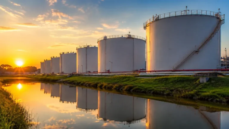
Automated Reactor Sampling
Automated Reactor Sampling
In modern chemical processing, pharmaceutical manufacturing, and water treatment, the transition from manual to automated reactor sampling represents a critical shift toward operational safety and analytical precision. Automated reactor sampling involves the systematic extraction of process fluids from a pressurized or vacuum-sealed vessel without exposing the operator or the environment to the contents. This process is intrinsically linked to accurate level measurement, as the success of a sampling cycle often depends on the precise knowledge of the liquid-gas interface within the reactor.
For engineers and plant managers, implementing an automated system requires a deep understanding of both the fluid dynamics within the vessel and the instrumentation that monitors those conditions. By integrating reliable level sensors with automated valves and sample conditioning units, facilities can achieve real-time process monitoring that manual methods cannot match.
Measurement Principles for Reactor Control
Before selecting an automated reactor sampling system, it is essential to understand the measurement principles that govern the reactor's environment. Accurate level measurement ensures that the sampling probe or dip tube is correctly positioned relative to the liquid surface, preventing the extraction of headspace gas or settled solids.
Radar Level Measurement
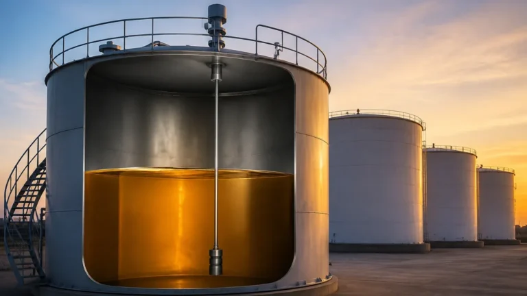
Radar level meters, particularly non-contact and guided wave varieties, are the gold standard for reactor monitoring. Non-contact radar emits microwave pulses that reflect off the surface of the medium. The time-of-flight (ToF) is measured to calculate the distance. This is ideal for automated reactor sampling because it remains unaffected by changes in pressure, temperature, or the presence of vapors. Guided Wave Radar (GWR) uses a probe to direct the signal, which is effective in low-dielectric fluids or where internal reactor structures might cause signal interference.
Ultrasonic Level Sensing
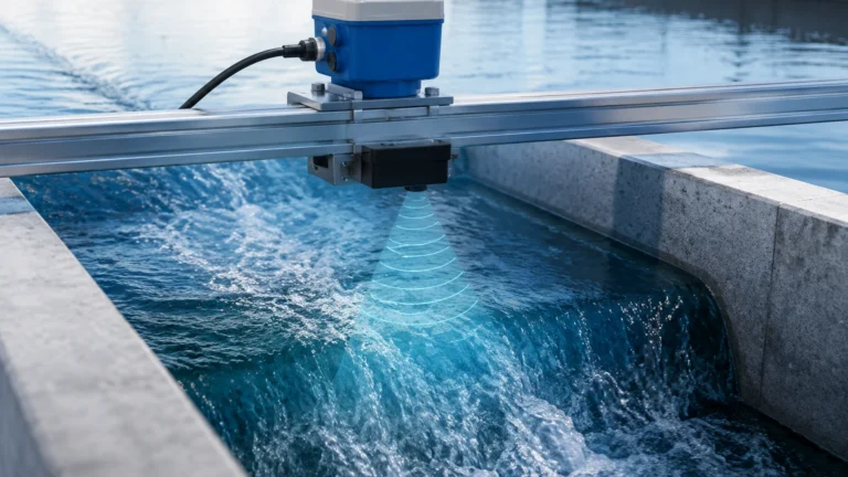
Ultrasonic sensors function by emitting high-frequency sound waves. While cost-effective for water treatment and atmospheric tanks, they have limitations in reactors involving high pressure (above 3 bar) or heavy foam, as these conditions can attenuate the sound signal. In automated sampling, ultrasonic sensors are typically used in secondary containment or buffer tanks rather than the primary high-pressure reactor.
Hydrostatic Pressure
Hydrostatic transmitters measure the pressure exerted by the liquid column. This principle is highly reliable for homogenous liquids. However, if the density of the reactor contents changes during a reaction—common in polymerization or fermentation—the level reading must be compensated. Accurate hydrostatic data is vital for ensuring the sampling pump has sufficient Net Positive Suction Head (NPSH).
For a detailed look at the instrumentation required to support these processes, professionals can refer to the Main Page of specialized industrial measurement providers.
The Role and Mechanics of Automated Reactor Sampling
Automated reactor sampling systems are designed to replace the "bucket and valve" method. Manual sampling often introduces variables such as operator technique, exposure to hazardous fumes, and the risk of sample contamination from the atmosphere. Automation standardizes the volume, timing, and cleaning of the sampling line.
How the System Operates
1. Initiation: The process control system (DCS or PLC) triggers a sampling cycle based on time or a specific process milestone (e.g., a temperature setpoint).
2. Purging: The system flushes the dead volume in the sampling line back into the reactor or to a waste header using an inert gas like Nitrogen ($N_2$). This ensures the sample is representative of the current reactor state.
3. Extraction: A precise volume of liquid is drawn through a dip tube or a side-mounted valve. In high-pressure reactors, the internal pressure drives the sample; in low-pressure vessels, a peristaltic or diaphragm pump is used.
4. Conditioning: The sample may pass through a heat exchanger to cool it to a safe handling temperature (e.g., from 150°C down to 25°C) or to prevent flashing of volatile components.
5. Collection or Analysis: The sample is either deposited into a sealed bottle via a needle-and-septum arrangement or diverted to an on-line analyzer (HPLC, GC, or Titrator).
6. Cleaning: The system performs a Clean-in-Place (CIP) cycle to prevent cross-contamination between batches.
Technical Selection Criteria
Choosing the right components for automated reactor sampling requires balancing chemical compatibility with mechanical reliability. The following table provides a comparison of common sampling configurations.
Selection Table: Sampling Configurations
| Feature | Dip Tube (Top Mount) | Side-Port Valve | Circulation Loop |
| :— | :— | :— | :— |
| Best For | Corrosive liquids, glass-lined reactors | High-viscosity fluids | Continuous monitoring/On-line analysis |
| Pressure Limit | Up to 40 bar | Up to 100+ bar | Dependent on pump rating |
| Maintenance | Easy to pull and inspect | Requires vessel drainage to service | Moderate; involves pump seals |
| Dead Volume | High (requires Nitrogen purge) | Low | Minimal if properly designed |
| Level Dependency | High; requires accurate level data | Low; must be below minimum level | Continuous flow required |
Material Compatibility
In chemical reactors, the wetted parts of the sampling system and the level meters must withstand aggressive media. Common materials include 316L Stainless Steel, Hastelloy C276, and PTFE linings. For level measurement, the antenna or probe material is just as critical as the sampling valve seal to prevent premature failure due to corrosion.
Installation and Engineering Best Practices
Proper installation is the difference between a representative sample and a failed batch. Engineers should adhere to the following guidelines:
* Avoid Dead Legs: The distance between the main process flow and the sampling valve should be minimized. Any stagnant fluid in this space will not represent the current reaction state.
* Slope for Drainage: All sampling lines should be sloped at a minimum of 1:50 toward the collection point or back to the reactor to ensure gravity drainage after the purge cycle.
* Integration with Level Meters: The automated sampling sequence should be interlocked with the level transmitter. If the level falls below the sampling point (e.g., during a transfer), the system must inhibit the sampling cycle to prevent pump damage or gas ingestion.
* Heat Tracing: For products that are solid at room temperature (e.g., resins or waxes), the entire sampling line must be steam or electric heat-traced and insulated to prevent clogging.

Limitations and Risk Mitigation
While automated reactor sampling offers numerous benefits, it is not without limitations. Understanding these risks is essential for robust process design.
1. Clogging and Solids Handling: If the reactor contains slurries or catalysts, the sampling probe can clog. Mitigation involves using high-pressure back-pulsing with solvent or gas to clear the orifice before and after each cycle.
2. Seal Integrity: Automated valves cycle frequently. In hazardous environments, a bellows seal or a double-block-and-bleed arrangement is recommended to prevent toxic leaks to the atmosphere.
3. Representative Accuracy: In unagitated or poorly mixed reactors, a single sampling point may not represent the entire volume. Engineers should confirm mixing efficiency before relying on automated data for batch release.
4. Data Synchronization: There is often a time lag between extraction and analysis. The control system must account for this delay when making real-time adjustments to the reactor temperature or feed rates.
Frequently Asked Questions (FAQs)
Q: How does the reactor pressure affect automated sampling?
A: If the reactor is pressurized (e.g., 5 bar), the pressure itself can be used to move the sample through the conditioning system. However, if the pressure is too high, specialized pressure-reducing valves are required to prevent "flashing," where the liquid turns to vapor instantly upon exit, ruining the sample integrity.
Q: Can automated sampling be used in sterile pharmaceutical environments?
A: Yes, but the system must be designed for SIP (Steam-in-Place). This involves using diaphragm valves and ensuring there are no crevices where bacteria can grow. Level sensors used in these applications should have a sanitary tri-clamp connection and a high surface finish (Ra < 0.8 μm).
Q: What happens if the level sensor fails during a sampling cycle?
A: This is a significant safety risk. Most modern systems use a "fail-safe" logic. If the signal from the level meter is lost or indicates an error, the sampling valves should automatically return to the closed position to prevent an uncontrolled release of process material.
Summary of Confirmations for Project Stakeholders
Before proceeding with an automated reactor sampling project, engineering teams should confirm the following:
* Chemical Compatibility: Ensure wetted parts of both the sampler and the level meters (Radar/Ultrasonic) are compatible with the process media.
* Process Conditions: Confirm maximum and minimum operating temperatures and pressures ($T_{max}$, $P_{max}$).
* Sample Volume: Define the exact volume required for analysis to size the sample loop correctly.
* Site Infrastructure: Ensure availability of instrument air, Nitrogen for purging, and electrical power for the control unit.
Automating the sampling process, when supported by accurate level measurement and robust valve technology, significantly enhances the reliability of industrial processes. By following these engineering principles, facilities can ensure safer operations and higher product quality. For further technical specifications and hardware options, visiting the Main Page of an industry leader in level measurement is a recommended next step for procurement and design teams.