Boiler Monitoring System
Boiler Monitoring System
In industrial thermal power generation and process heating, the boiler monitoring system serves as the primary safeguard for operational continuity and personnel safety. Effective monitoring focuses on the precise control of water levels, steam pressure, and temperature within the boiler drum and associated feed systems. Given the extreme conditions—characterized by high temperatures, fluctuating pressures, and the presence of saturated steam—selecting the correct instrumentation is a critical engineering decision.
This guide examines the technical principles of level measurement within a boiler monitoring system, provides selection criteria for various technologies, and outlines best practices for installation and maintenance in high-demand industrial environments.
Core Principles of Level Measurement in Boilers
Before selecting hardware for a boiler monitoring system, it is essential to understand the physical principles governing how level is detected in high-pressure steam environments. The three most common methods include buoyancy, hydrostatic pressure, and microwave reflection.
Buoyancy and Magnetic Coupling
Magnetic level gauges operate on the principle of buoyancy. A float containing a permanent magnet assembly is placed inside a bypass chamber connected to the boiler drum. As the water level rises or falls, the float moves accordingly. This magnetic field acts upon an external indicator rail or a transmitter. Because the measurement is mechanical and magnetic, it provides a clear visual local indication without requiring a power source, which is vital for manual safety checks.
Hydrostatic Differential Pressure
Differential pressure (DP) transmitters measure the head pressure of the liquid column. In a boiler, the transmitter compares the pressure at the bottom of the drum to the steam pressure at the top. The difference between these two points, adjusted for the density of the water at operating temperature, determines the level. This method is a legacy standard but requires careful compensation for density changes as the boiler heats up.
Guided Wave Radar (GWR)
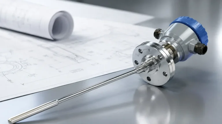
Guided Wave Radar utilizes Time Domain Reflectometry (TDR). Low-power microwave pulses are sent down a probe (waveguide). When these pulses hit the surface of the water, which has a higher dielectric constant than the steam above it, a portion of the energy is reflected back to the transmitter. The system measures the time of flight to calculate the distance. In a boiler monitoring system, GWR is often preferred because it is less affected by changes in fluid density compared to hydrostatic or buoyancy-based methods.
Technology Selection for Boiler Monitoring
Choosing the right instrument depends on the specific boiler type (e.g., fire-tube vs. water-tube), operating pressure, and the level of automation required. The following table compares the primary technologies used in modern industrial boiler applications.
| Technology | Typical Pressure Range | Max Temperature | Advantages | Limitations |
| :— | :— | :— | :— | :— |
| Magnetic Level Gauge | Up to 200 bar | 450°C | Highly visible; no power needed for local display; robust. | Requires bypass chamber; density-dependent. |
| Guided Wave Radar | Up to 400 bar | 450°C | High accuracy; not density-dependent; no moving parts. | High-pressure steam requires dielectric compensation. |
| Differential Pressure | Unlimited | Process Limited | Well-understood; easy to dual-purpose for flow. | Complex impulse line installation; high maintenance. |
| Conductivity Probes | Up to 250 bar | 370°C | Excellent for point level/alarm; fast response. | Not suitable for continuous 0-100% measurement. |
For a comprehensive overview of available instrumentation for these systems, engineers can Review product options and application support at the Welk Main Page.
Critical Components of an Integrated System
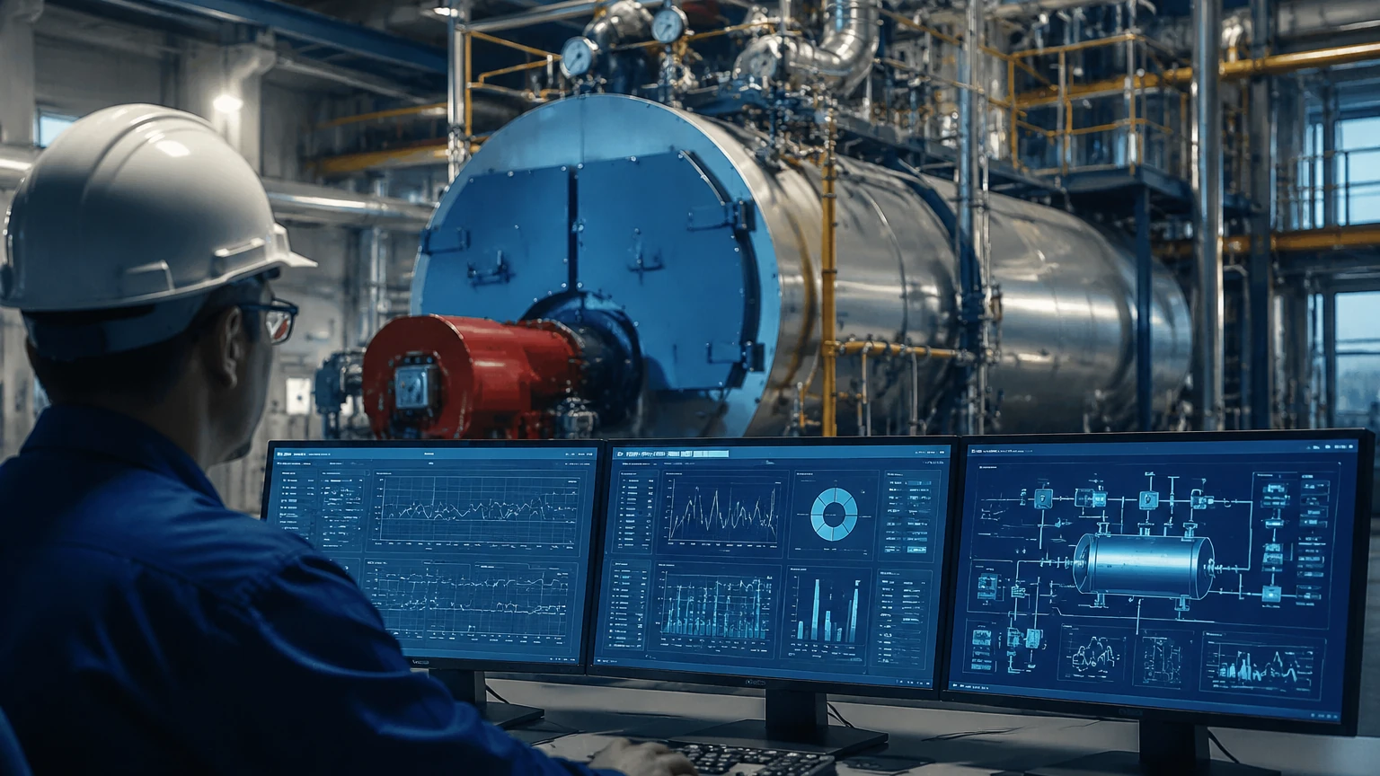
A robust boiler monitoring system is more than just a single sensor; it is a multi-layered architecture designed to prevent "low water" conditions, which can lead to boiler explosions, or "high water" conditions, which cause moisture carryover into turbines.
1. Continuous Level Transmitters: Usually GWR or DP transmitters that provide a 4-20mA or digital signal (HART, Foundation Fieldbus) to the Feedwater Control System.
2. Visual Indicators: Magnetic level gauges or glass gauges that allow operators to verify electronic readings during rounds.
3. High/Low Alarms and Cut-offs: Independent level switches (often float or conductivity-based) that trigger an Emergency Pressure Relief or Fuel Shut-off if levels cross safety thresholds.
4. Steam Quality Monitoring: Pressure and temperature transmitters that work alongside level sensors to ensure the steam is within the required saturation parameters.
Installation Considerations for High-Pressure Steam
The accuracy of a boiler monitoring system is heavily influenced by how the instruments are installed. High-temperature environments require specific mechanical configurations to protect the electronics and ensure signal integrity.
Bypass Chambers and Bridles
Most boiler level instruments are installed in an external bypass chamber (also known as a bridle) rather than directly in the drum. This isolates the sensor from the turbulence of the boiling surface and allows for maintenance without shutting down the boiler. It is critical that the piping between the drum and the chamber is sufficiently large (typically 25mm to 50mm) to prevent clogging and ensure the level in the chamber accurately tracks the level in the drum.
Temperature Dissipation
While the probe or float is rated for high temperatures, the transmitter electronics often are not. Use of cooling extensions or remote-mounted electronics is recommended when process temperatures exceed 150°C. This prevents thermal drift and extends the lifespan of the internal capacitors and processors.
Steam Compensation in Radar
In high-pressure saturated steam (above 10 bar), the dielectric constant of the steam space increases. This slows down the microwave signal of a Guided Wave Radar, leading to a "negative error" where the reported level is lower than the actual level. Modern radar units used in a boiler monitoring system include a reference pole or a specialized software algorithm to compensate for this effect automatically.
Common Risks and Mitigation
Operating a boiler monitoring system involves managing several inherent risks that can compromise data accuracy:
* Scaling and Build-up: In untreated water, mineral deposits can form on radar probes or float mechanisms. Regular blow-down of the bypass chamber is required to clear sediment.
* Ambient Temperature Fluctuations: For DP transmitters, the density of the water in the "wet leg" (reference leg) can change if ambient temperatures shift, leading to errors. Insulation of the impulse lines is a standard mitigation strategy.
* Vibration: Industrial boilers often involve high-velocity steam and heavy machinery. Sensors must be rated for high-vibration environments, and support brackets should be used for long probes to prevent mechanical fatigue.
Maintenance and Calibration Protocols
To maintain the reliability of the boiler monitoring system, a structured maintenance schedule is mandatory. This typically includes:
* Monthly Visual Inspection: Check for leaks at flanges and gaskets, and ensure the magnetic indicator moves freely.
* Quarterly Blow-down: Flush the bypass chamber to remove accumulated sludge or scale.
* Annual Calibration: Verify the 4-20mA output against a known physical level. For Guided Wave Radar, this can often be done via software diagnostics without removing the probe.
* Proof Testing: Periodically trigger the high and low-level cut-offs to ensure the safety interlocks are functional. This is often a requirement for insurance and regulatory compliance (such as ASME or PED standards).
Frequently Asked Questions (FAQ)
Q: Can I use ultrasonic sensors for boiler drum level?
A: Generally, no. Ultrasonic sensors rely on sound waves, which are significantly affected by changes in air density, temperature, and the presence of heavy steam. Guided Wave Radar or Magnetic Gauges are far more reliable for these conditions.
Q: What is the difference between a level transmitter and a level switch in a boiler?
A: A transmitter provides a continuous signal (e.g., 45% full), which is used for modulating the feedwater valve. A switch is a point-level device (On/Off) used specifically for safety interlocks, such as shutting off the burner if the water drops too low.
Q: How does steam pressure affect magnetic level gauges?
A: As pressure increases, the density of water decreases while the density of the float remains constant. This causes the float to sink slightly deeper into the water. High-pressure magnetic gauges must be calibrated for the specific operating gravity of the fluid at its working temperature.
Conclusion for Project Engineers
Implementing an effective boiler monitoring system requires a balance between redundant safety features and high-accuracy process control. While Guided Wave Radar offers the most advanced technical performance regarding density independence, the mechanical reliability of Magnetic Level Gauges remains a staple for visual verification.
Before finalizing a specification, project teams should confirm the maximum operating pressure (MAWP), the chemical composition of the feedwater, and the required safety integrity level (SIL). For further technical specifications and to explore high-performance level measurement hardware, visit the Welk Main Page.