Boiler Monitoring Systems
Boiler Monitoring Systems
In industrial thermal energy production, boiler monitoring systems represent the critical interface between operational efficiency and catastrophic risk management. These systems are designed to provide real-time data on the internal states of a boiler—most notably water level, pressure, and temperature—to ensure that the steam generation process remains within safe design parameters. For plant engineers and facility managers, selecting the correct instrumentation is not merely a matter of measurement; it is a requirement for regulatory compliance and the prevention of equipment failure.
Effective boiler monitoring relies on a suite of sensors that can withstand the extreme conditions of high-pressure steam environments. Because water level is the most volatile and critical variable in a steam drum, the technologies used to track it must be robust, redundant, and highly accurate. This guide explores the engineering principles behind these systems and provides a framework for selecting and installing the appropriate level measurement technology.
Principles of Level Measurement in Boiler Environments
Measuring the level of water in a pressurized boiler is significantly more complex than measuring fluids in ambient storage tanks. The primary challenges include high temperatures, high pressures, and the presence of saturated steam. To navigate these challenges, several physical principles are employed.
Hydrostatic Pressure Principle
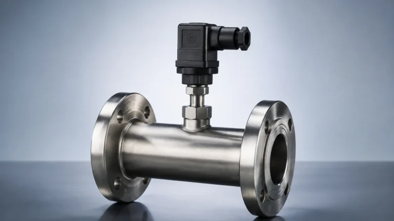
Hydrostatic level measurement operates on the principle that the pressure at a specific point in a liquid is proportional to the height of the liquid column above it. The formula $P = \rho gh$ (where $P$ is pressure, $\rho$ is density, $g$ is gravity, and $h$ is height) defines this relationship. In boiler monitoring systems, differential pressure (DP) transmitters are often used. They measure the difference between the pressure at the bottom of the drum and the pressure in the steam space above the water.
However, a critical factor in boiler applications is that the density ($\rho$) of water changes significantly as temperature increases. For example, water at 20°C has a density of approximately 998 kg/m³, but at 250°C (typical for high-pressure boilers), the density drops to roughly 799 kg/m³. Without active density compensation through temperature monitoring, a hydrostatic sensor will report an incorrect level.
Guided Wave Radar (GWR)
Guided Wave Radar utilizes Time Domain Reflectometry (TDR). The sensor emits a low-energy microwave pulse down a physical probe (waveguide). When the pulse hits the surface of the water, a portion of the energy is reflected back to the transmitter because of the change in the dielectric constant between the steam and the water. The time it takes for the pulse to travel down and back is used to calculate the distance. Unlike hydrostatic methods, GWR is less affected by changes in fluid density. However, in high-pressure steam, the dielectric constant of the steam itself increases, which can slow down the microwave pulse. Advanced boiler monitoring systems use "gas phase compensation" probes that feature a mechanical target at a fixed distance to calibrate the signal speed in real-time.
Magnetic Buoyancy
Magnetic level gauges utilize a float containing a high-strength magnet. As the water level in a bypass chamber (connected to the boiler) rises or falls, the float moves accordingly. This magnetic field acts upon an external indicator or a reed-switch transmitter. This provides a clear visual indication for operators while simultaneously sending an electronic signal to the control room. Because the float is the only moving part in contact with the process, this method is highly reliable for high-pressure applications where direct contact with electronic sensors might be risky.
Components of Integrated Boiler Monitoring Systems
A comprehensive system for boiler oversight consists of more than just a single sensor. It is an integrated network of hardware and software designed for redundancy.
1. Primary Level Sensors: These are the continuous measurement devices, such as Guided Wave Radar or DP transmitters, that provide the 4-20mA or digital signal (HART, Modbus) to the control system.
2. Low-Level Cut-Offs (LLCO): These are safety-critical switches. If the water level drops below a predetermined safety point, the LLCO automatically shuts down the fuel supply to the burner to prevent "dry firing," which can lead to boiler explosion.
3. High-Level Alarms (HLA): These prevent water from entering the steam lines (carryover). Water in steam lines can cause "water hammer," which destroys turbines and piping systems.
4. Bypass Chambers and Bridles: These external vessels allow for the mounting of multiple instruments outside the main boiler shell, facilitating maintenance without shutting down the entire boiler.
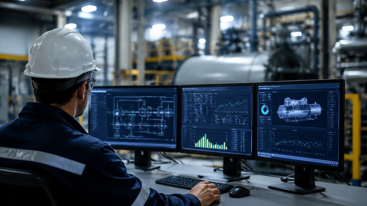
5. Control Interface: This is the PLC or dedicated boiler controller that processes sensor data and manages the feed-water pumps and blowdown valves.
For those seeking specific hardware configurations and technical specifications for these components, you can Review product options and application support at Welk’s Main Page.
Technology Selection Criteria
Choosing the right technology for boiler monitoring systems requires an analysis of the boiler’s operating class. A low-pressure heating boiler in a commercial building has different requirements than a high-pressure recovery boiler in a chemical plant.
| Technology | Max Temperature | Max Pressure | Best Application | Primary Limitation |
| :— | :— | :— | :— | :— |
| Differential Pressure | Up to 400°C | Up to 400 bar | High-pressure utility boilers | Requires complex density compensation |
| Guided Wave Radar | Up to 450°C | Up to 400 bar | Saturated steam drums | Steam dielectric changes require compensation |
| Magnetic Level Gauge | Up to 400°C | Up to 320 bar | Visual local indication | Float can be damaged by rapid pressure surges |
| Ultrasonic Sensors | Up to 150°C | Up to 3 bar | Non-pressurized condensate tanks | Cannot be used in steam (sound speed variance) |
| Hydrostatic (Submersible) | Up to 80°C | N/A | Feedwater storage tanks | Not suitable for high-temp boiler internals |
Installation Considerations and Best Practices
The reliability of boiler monitoring systems is often determined during the installation phase. Even the most accurate radar level meter will fail if it is improperly mounted.
Heat Dissipation
While the probe of a sensor must withstand the internal boiler temperature, the electronics (the transmitter head) often have lower thermal limits (typically around 80°C). When installing sensors on steam drums, use cooling fins or remote-mounted electronics to prevent the heat from the boiler shell from frying the circuitry.
Stilling Wells and Bypass Chambers
Boiler internals are turbulent environments. The boiling action creates bubbles and surface fluctuations. To obtain a stable reading, sensors should be installed in a stilling well (a pipe inside the drum) or a bypass chamber (a pipe outside the drum). This isolates the sensor from turbulence while ensuring the level in the chamber matches the level in the drum.
Insulation and Heat Tracing
For bypass chambers, it is vital to insulate the chamber. If the water in the external chamber cools significantly compared to the water inside the boiler, the density difference will cause the level in the chamber to be lower than the actual level in the boiler (the "cold leg" effect). This can lead to dangerous overfilling.
Limitations and Common Risks
Engineers must be aware of the physical limitations of boiler monitoring systems to prevent false readings.
* The "Shrink and Swell" Phenomenon: When a boiler's steam demand suddenly increases, the pressure drops. This causes steam bubbles below the water surface to expand, making the water level appear to rise ("swell") even though the mass of water hasn't changed. Conversely, adding cold feedwater causes bubbles to collapse, making the level "shrink." Monitoring systems must be programmed with logic to account for these transient states.
* Foaming: High concentrations of dissolved solids in the boiler water can cause foam. Most radar and ultrasonic sensors will struggle to distinguish between the top of the foam and the actual liquid level. Regular boiler blowdown and chemical treatment are necessary to maintain the integrity of level measurements.
* Scaling and Buildup: In hard water environments, calcium and other minerals can build up on probes or inside bypass chambers. For magnetic gauges, this can cause the float to stick. Periodic inspection and cleaning are mandatory.
Frequently Asked Questions (FAQs)
Q: Can I use a standard ultrasonic level sensor for boiler drum monitoring?
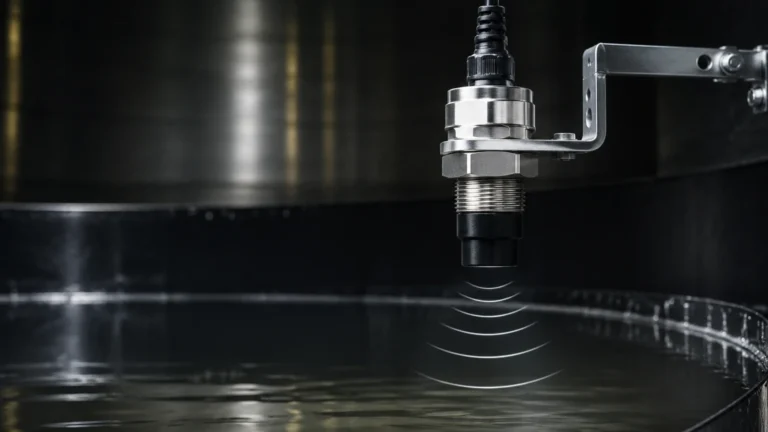
No. Ultrasonic sensors rely on the speed of sound through air. In a boiler, the atmosphere is saturated steam, and the speed of sound changes drastically with temperature and pressure fluctuations. Furthermore, the high-pressure environment can damage the transducer face. Guided Wave Radar or DP transmitters are the industry standard for these applications.
Q: Why is a 3-element control system better than a 1-element system?
A 1-element system only looks at the water level. A 3-element boiler monitoring system looks at the water level, the steam flow rate, and the feedwater flow rate. This allows the system to anticipate "shrink and swell" and provide much more stable control during rapid load changes.
Q: How often should boiler level switches be tested?
Safety-critical switches like the Low-Level Cut-Off (LLCO) should be tested daily or weekly depending on local jurisdictions and insurance requirements. This is usually done via a "blowdown" test, where the water level in the sensor chamber is manually lowered to ensure the burner shuts off.
Q: Is Guided Wave Radar affected by the heavy steam in the drum?
Standard GWR can be affected because steam has a higher dielectric constant than air, which slows down the radar signal and makes the level appear lower than it is. However, Welk offers GWR units with gas phase compensation that use a reference reflection to automatically correct for this error, maintaining accuracy within millimeters.
Conclusion
Boiler monitoring systems are the backbone of industrial steam safety. By understanding the physical principles of hydrostatic pressure, buoyancy, and microwave reflection, engineers can specify instrumentation that provides both accuracy and longevity. Whether utilizing a magnetic level gauge for clear visual confirmation or a Guided Wave Radar for high-precision digital control, the goal remains the same: maintaining the delicate balance of the steam-water interface. For comprehensive technical data and to explore the full range of industrial level measurement solutions, visit the Welk Main Page to find the right equipment for your specific boiler configuration.