Resistivity Transmitter
Resistivity Transmitter
In high-purity water applications, such as semiconductor manufacturing, pharmaceutical production, and power plant boiler feed systems, the measurement of ionic impurities is critical. A resistivity transmitter serves as the primary interface for monitoring these impurities by measuring the electrical resistance of a liquid. This guide provides a comprehensive overview of resistivity measurement principles, selection criteria, and installation best practices for industrial engineering environments.
Principles of Resistivity Measurement
Resistivity is the mathematical inverse of conductivity. While conductivity measures a fluid's ability to conduct an electrical current, resistivity measures how strongly a fluid opposes that current. In the context of water treatment, high resistivity indicates a low concentration of dissolved ions, signifying high purity.
The Fundamental Physics
The basic measurement relies on Ohm’s Law ($V = I \times R$). A resistivity transmitter applies an alternating current (AC) voltage to two or more electrodes immersed in the process liquid. By measuring the resulting current, the instrument determines the resistance ($R$) of the solution.
However, resistance is dependent on the geometry of the sensor. To standardize this, we use the Cell Constant ($K$), which is the ratio of the distance between electrodes ($L$) to the cross-sectional area of the electrodes ($A$):
$$K = L / A$$
Resistivity ($\rho$) is then calculated as:
$$\rho = R / K$$
In industrial applications, resistivity is typically expressed in Megohm-centimeters (M$\Omega\cdot$cm). Pure water has a theoretical maximum resistivity of approximately 18.18 M$\Omega\cdot$cm at 25°C (77°F).
Temperature Compensation
Resistivity is highly sensitive to temperature changes. As temperature increases, the mobility of ions in the water increases, which lowers the resistivity even if the actual ion concentration remains constant. To provide a standardized reading, a resistivity transmitter must perform automatic temperature compensation (ATC).
Most modern sensors incorporate a Resistance Temperature Detector (RTD), such as a Pt100 or Pt1000, located close to the electrodes. The transmitter uses an algorithm—often based on a non-linear compensation curve for ultrapure water—to calculate what the resistivity would be at a reference temperature, typically 25°C.
Resistivity vs. Conductivity: When to Use Which?
While both parameters describe the same physical property, the choice of units depends on the purity level of the process media.
| Feature | Conductivity Transmitter | Resistivity Transmitter |
| :— | :— | :— |
| Primary Unit | Microsiemens per cm ($\mu$S/cm) | Megohm-centimeters (M$\Omega\cdot$cm) |
| Application | Raw water, cooling towers, wastewater | Ultrapure water (UPW), deionized water |
| Ion Concentration | Moderate to High | Very Low |
| Typical Range | 0.055 $\mu$S/cm to 2,000 mS/cm | 0.02 to 18.2 M$\Omega\cdot$cm |
For engineers designing systems for industrial automation, understanding this distinction is vital. When the water quality reaches a point where conductivity values fall below 1 $\mu$S/cm, resistivity becomes the more practical and precise unit of measurement. For broader industrial measurement needs, including tank levels and process control, manufacturers like Welk provide integrated solutions that complement water quality monitoring.
Key Components of a Resistivity Measurement System
A complete measurement loop consists of three main parts:
1. The Sensor (Cell): Contains the electrodes and the temperature element. For resistivity, these are almost always contact-type sensors with low cell constants (typically $K=0.01$ or $K=0.1$).
2. The Cable: Connects the sensor to the transmitter. In high-purity applications, cable quality and shielding are critical to prevent electromagnetic interference from distorting the high-resistance signal.
3. The Transmitter: The electronic unit that provides the excitation voltage, processes the return signal, applies temperature compensation, and outputs a signal (such as 4-20mA, Modbus, or HART) to a PLC or DCS.
Selection Criteria for Resistivity Transmitters
Selecting the correct resistivity transmitter requires a detailed understanding of the process environment. Use the following table as a baseline for evaluation:
| Criteria | Specification Requirement | Engineering Consideration |
| :— | :— | :— |
| Measurement Range | 0–20 M$\Omega\cdot$cm | Ensure the transmitter resolution is sufficient for the target purity. |
| Cell Constant ($K$) | 0.01 cm⁻¹ | Low constants are required for high-sensitivity measurements. |
| Process Connection | NPT, Flange, or Tri-Clamp | Must match existing piping and hygiene requirements (e.g., 3-A, EHEDG). |
| Wetted Materials | 316L SS, Titanium, PEEK | Materials must not leach ions back into the ultrapure water. |
| Output Protocol | 4-20mA / RS485 | Compatibility with the facility's control system. |
| Enclosure Rating | IP66 / NEMA 4X | Necessary for wash-down or outdoor environments. |
Installation Considerations
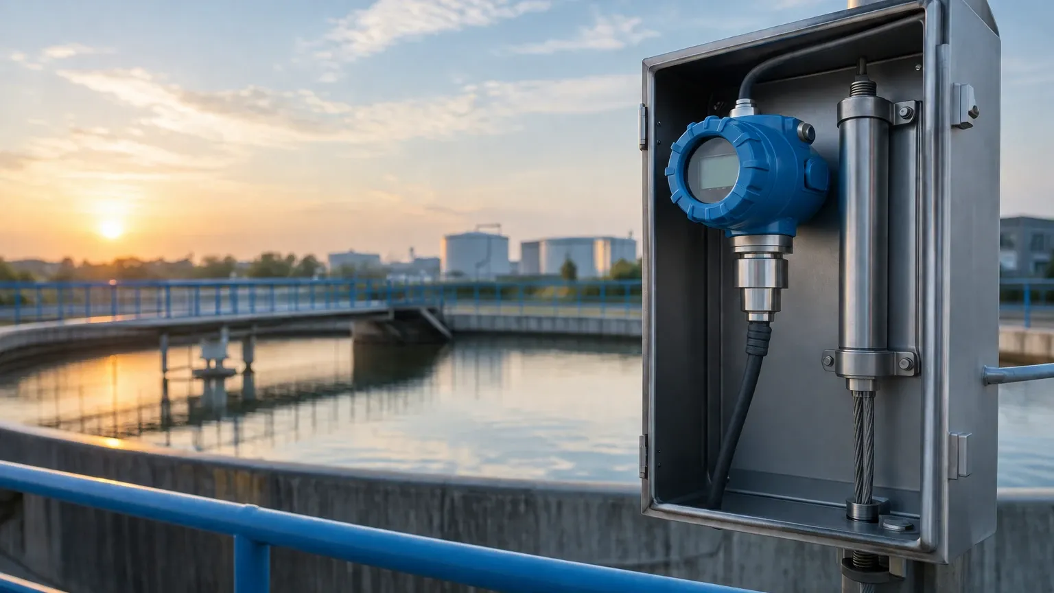
Correct installation is as important as the instrument's specifications. Even the most accurate resistivity transmitter will provide false data if the sensor is improperly placed.
Sensor Orientation and Flow
* Full Immersion: The sensor must be completely submerged in the liquid at all times. Avoid installing sensors at the top of a horizontal pipe where air pockets can form.
* Flow Direction: It is generally recommended to install the sensor in a vertical pipe with the flow moving upward. This ensures that the sensor remains flooded and helps sweep away any stray bubbles.
* Representative Sampling: The sensor should be placed in a location where the flow is turbulent enough to be representative of the bulk fluid but not so violent that it causes cavitation.
Electrical and Wiring
* Cable Length: Minimize the distance between the sensor and the transmitter. Long cable runs increase the risk of signal degradation and noise pickup. If long distances are unavoidable, use a transmitter with a pre-amplifier or a digital sensor protocol.
* Grounding: Ensure the transmitter and the process piping are properly grounded. Ground loops are a common source of measurement drift in resistivity systems.
Limitations and Common Risks
Engineers should be aware of the factors that can compromise resistivity measurement accuracy:
1. Fouling and Scaling: Although resistivity is measured in clean water, over time, a biofilm or mineral scale can develop on the electrodes. This increases the measured resistance, leading to an erroneously high resistivity reading.
2. Air Bubbles: Air is an insulator. If bubbles accumulate on the electrode surface, the transmitter will interpret this as a higher resistance (higher purity) than actually exists.
3. Chemical Incompatibility: While 316L stainless steel is standard, certain aggressive deionizing chemicals may require titanium or specialized plastic electrodes to prevent corrosion.
4. Polarization: Using a DC voltage for measurement would cause ions to migrate and cluster at the electrodes, creating a "false resistance." This is why all modern resistivity transmitters use an AC excitation frequency.
Maintenance and Calibration
Unlike level meters or pressure sensors, resistivity sensors cannot be easily calibrated using a "zero and span" method in the field because it is nearly impossible to maintain a stable, known-purity water sample without contamination from the atmosphere (CO₂ absorption rapidly lowers resistivity).
Instead, calibration is typically performed via:
* Electronic Verification: Using precision resistors to simulate a specific resistivity value to check the transmitter's electronics.
* Comparison Calibration: Comparing the online sensor reading against a recently calibrated portable master meter in a side-by-side flow cell.
For organizations looking to integrate these measurements into a broader process control framework, visiting the Main Page of a dedicated instrument manufacturer can provide insights into how water quality data can be paired with level and flow monitoring for total system automation.
Frequently Asked Questions (FAQs)
Q: Why does my resistivity drop as soon as the water is exposed to air?
A: Carbon dioxide (CO₂) from the air dissolves into the water, forming carbonic acid. This acid dissociates into ions, which increases conductivity and causes the resistivity to drop significantly (often from 18 M$\Omega\cdot$cm down to 1–2 M$\Omega\cdot$cm in minutes).
Q: Can I use a resistivity transmitter for wastewater applications?
A: No. Wastewater has high ion concentrations, meaning the resistivity would be near zero. In these cases, a conductivity transmitter with a high cell constant or a toroidal (inductive) sensor is required.
Q: How often should I replace the resistivity sensor?
A: In ultrapure water, sensors can last several years because there is little to no chemical attack or fouling. Replacement is usually only necessary if the electrodes become physically damaged or if the internal temperature sensor fails.
Q: What is the difference between a 2-electrode and a 4-electrode sensor for resistivity?
A: For high-purity water (high resistivity), 2-electrode sensors are the industry standard because they are highly sensitive to low ion concentrations. 4-electrode sensors are designed to ignore fouling and are typically used in high-conductivity applications.
By following these engineering guidelines and selecting robust hardware, operators can ensure the long-term reliability of their water purity monitoring systems. For more information on industrial instrumentation and measurement solutions, explore the resources available on the Main Page.