Calorimetric Flow Meter
Calorimetric Flow Meter
In the landscape of industrial process control, the calorimetric flow meter—often referred to as a thermal mass flow meter or thermal dispersion flow meter—represents a critical instrument for measuring the flow rate of gases and liquids. Unlike mechanical flow meters that rely on moving parts or differential pressure devices that require complex calculations to derive mass flow, calorimetric sensors utilize the thermal properties of the fluid itself. This technology is particularly valued in B2B sectors such as wastewater treatment, chemical processing, and compressed air management due to its high sensitivity at low flow rates and its ability to provide direct mass flow measurement without additional pressure or temperature compensation.
Measurement Principles of Calorimetric Flow Meters
The fundamental operation of a calorimetric flow meter is based on the physical principle of heat transfer. When a heated object is placed in a flowing fluid, the fluid carries heat away from the object. The rate at which this heat is dissipated is directly proportional to the mass flow rate of the fluid. This relationship is often described by King’s Law, which relates the heat loss from a cylinder to the velocity of the fluid moving past it.
In practical industrial applications, two primary methods are employed to utilize this principle:
1. Constant Temperature Differential
In this configuration, the meter utilizes two sensors, typically Resistance Temperature Detectors (RTDs). One sensor acts as a reference, measuring the ambient temperature of the fluid. The second sensor is heated to a specific, constant temperature above the fluid temperature (e.g., a differential of 30°C). As the fluid flows, it cools the heated sensor. To maintain the constant temperature differential, the electronic circuit must increase the power supplied to the heater. This electrical power consumption is the measurement signal, which is then linearized and calibrated to represent the mass flow rate.
2. Constant Power Method
In the constant power approach, a fixed amount of electrical energy is supplied to the heated sensor. As the flow rate increases, the temperature of the heated sensor decreases because more heat is being carried away by the fluid. The temperature difference between the heated sensor and the reference sensor is measured. At high flow rates, the temperature difference is small, while at low flow rates, the difference is large. While robust, this method is often less sensitive at the high end of the flow range compared to the constant temperature method.
Because these instruments measure the molecular heat transfer, they are measuring mass flow rather than volumetric flow. This is a significant advantage in gas applications where volume changes drastically with fluctuations in pressure and temperature.
Key Components and Construction
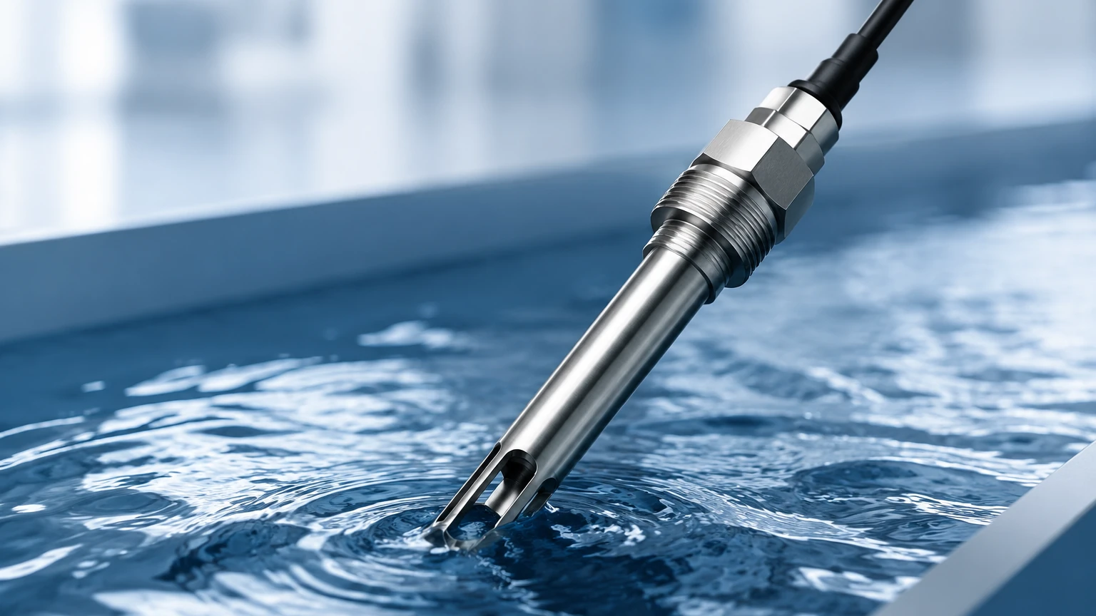
A calorimetric flow meter generally consists of a probe assembly and a transmitter (electronics). The probe is the part that interfaces directly with the process media.
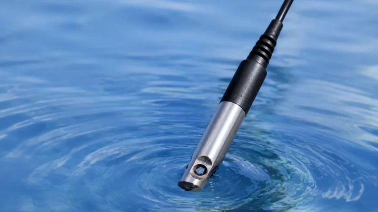
* The Sensors: Most high-quality industrial meters use platinum RTDs (such as Pt100 or Pt1000) encased in protective metal thermowells (usually 316L stainless steel or Hastelloy). This protects the delicate sensors from corrosion and mechanical wear.
* The Probe Body: For smaller pipes, the sensors are mounted within an inline flow body. For larger ducts or pipes (typically above 80mm), an insertion-style probe is used, allowing the meter to be installed through a flange or a compression fitting.
* The Transmitter: The electronics convert the raw thermal data into standard industrial outputs, such as 4-20mA, pulse, or digital protocols like Modbus or HART. Modern transmitters also include diagnostic features to monitor sensor health.
Selection Criteria for Industrial Applications
Choosing the correct calorimetric flow meter requires a thorough understanding of the process conditions. Unlike level measurement instruments where the primary concern is the surface of the media, flow measurement requires an understanding of the fluid's thermal conductivity and viscosity. For those integrating these sensors into broader automation systems, it is often helpful to Review product options and application support to ensure compatibility with existing level and pressure monitoring infrastructure.
Practical Selection Table
| Parameter | Requirement/Specification | Consideration |
| :— | :— | :— |
| Fluid State | Clean Gas or Liquid | Not suitable for highly abrasive slurries. |
| Pipe Diameter | 10 mm to 6,000 mm | Insertion probes are cost-effective for large diameters. |
| Flow Velocity | 0.1 m/s to 150 m/s (Gas) | Excellent for low-flow leak detection. |
| Operating Temperature | -40°C to +250°C | High-temp versions require special cooling fins. |
| Operating Pressure | Up to 40 bar (standard) | High-pressure applications require thicker thermowells. |
| Accuracy | ±1% of Reading | Requires stable fluid composition. |
Installation Considerations
To achieve the specified accuracy, the installation of a calorimetric flow meter must follow strict engineering guidelines. The most critical factor is the flow profile. Thermal dispersion sensors measure a point velocity (in insertion models) or a localized average (in inline models). For the reading to be accurate, the flow must be "fully developed" and laminar.
1. Straight Run Requirements: Generally, a minimum of 10 to 20 diameters (10D – 20D) of straight pipe is required upstream of the sensor, and 5 diameters (5D) downstream. If there are valves, elbows, or reducers closer than this, flow conditioners (vanes) may be necessary to prevent turbulence.
2. Orientation: For liquid applications, the pipe must always be full. Therefore, vertical upward flow is preferred. For gas applications, horizontal installation is common, but the sensor should be positioned at the side of the pipe (3 o'clock or 9 o'clock position) to avoid moisture accumulation on the probe tip.
3. Insertion Depth: For insertion meters, the sensor must be placed at the point of average velocity, which is typically at the center of the pipe for laminar flow. Incorrect depth is a leading cause of measurement error.
Limitations and Common Risks
While highly versatile, the calorimetric flow meter is not a universal solution. Engineers must be aware of the following limitations:
* Fluid Composition Sensitivity: Since the meter is calibrated for the specific thermal conductivity of a fluid, any change in the fluid's composition will result in errors. For example, a meter calibrated for pure Nitrogen will not provide accurate readings if the gas stream changes to a Nitrogen-CO2 mix.
* Moisture and Droplets: In gas applications, the presence of liquid droplets (condensate) can cause significant measurement spikes. When a droplet hits the heated sensor, it absorbs a large amount of heat as it evaporates, which the meter interprets as a sudden burst of high-velocity gas.
* Coating and Scaling: If the process media is prone to leaving deposits (such as fats in food processing or scale in hard water), the coating on the probe acts as an insulator. This slows down the heat transfer and causes the meter to under-read the actual flow.
Comparison with Level Measurement Technologies
In many industrial B2B environments, flow and level measurement work in tandem. While a calorimetric flow meter monitors the rate of fluid entering a vessel, instruments like radar level meters or ultrasonic sensors monitor the total volume stored. In water treatment plants, for instance, a flow meter measures the aeration air being pumped into a tank, while a hydrostatic level transmitter ensures the tank does not overflow. For a comprehensive overview of how these technologies integrate, users often refer to the Main Page for technical documentation on level-to-flow synchronization.
Frequently Asked Questions (FAQs)
Q: Can a calorimetric flow meter measure steam?
A: Generally, no. The high temperature and the phase-change nature of steam (condensing into droplets) make it unsuitable for standard thermal dispersion technology. Vortex or differential pressure meters are typically used for steam.
Q: Does the meter need to be recalibrated if the pressure changes?
A: No. One of the primary benefits of this technology is that it measures mass flow. Because mass does not change with pressure, the meter remains accurate regardless of pressure fluctuations, provided the gas remains within the calibrated range.
Q: How do I maintain the sensor?
A: Maintenance is minimal due to the lack of moving parts. Periodic inspection for coating or corrosion is recommended. If the fluid is dirty, many insertion meters can be equipped with a "hot tap" retractor, allowing the sensor to be removed for cleaning without shutting down the process line.
Q: What is the typical response time?
A: Because the sensors are encased in protective thermowells, there is a slight thermal lag. Typical response times range from 1 to 2 seconds, which is sufficient for most process control loops but may be too slow for high-speed batching applications.
Conclusion
The calorimetric flow meter is a robust, reliable, and cost-effective tool for mass flow measurement in modern industry. By understanding the underlying principles of thermal dispersion and adhering to strict installation standards, engineers can achieve highly accurate data for gas and liquid processes. Whether it is used for monitoring cooling water in a chemical plant or managing compressed air costs in a factory, this technology provides the precision required for efficient operations. For those seeking to pair these flow solutions with advanced level instrumentation, consulting a professional manufacturer ensures that the entire measurement loop is optimized for the specific demands of the application.