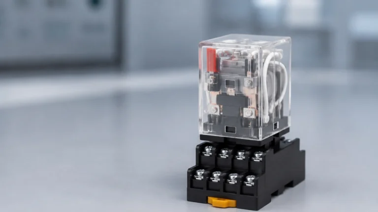
Promag W400
Promag W400
In the landscape of industrial process automation, electromagnetic flow measurement stands as one of the most reliable methods for monitoring conductive liquids. Among the specialized instruments in this category, the Promag W400 series represents a significant segment of the market, particularly for water and wastewater applications. While level measurement technologies—such as radar, ultrasonic, and hydrostatic sensors provided by manufacturers like Welk—are essential for inventory management and tank monitoring, electromagnetic flowmeters like the Promag W400 provide the critical data needed for dynamic process control and billing.
Understanding the engineering principles, selection criteria, and installation requirements of the Promag W400 is vital for engineers tasked with designing efficient fluid handling systems. This guide explores the technical foundations of electromagnetic flow measurement and provides a practical framework for evaluating this technology alongside complementary level measurement solutions.
Measurement Principles of Electromagnetic Flowmeters
Before selecting a specific instrument like the Promag W400, it is essential to understand the physics governing its operation. Electromagnetic flowmeters operate based on Faraday’s Law of Induction. This principle states that a conductor moving through a magnetic field induces an electrical voltage within that conductor.
The Faraday Equation
In the context of industrial flow measurement, the conductive liquid acts as the moving conductor. The pipe is surrounded by two electromagnetic coils that generate a constant magnetic field. As the liquid flows through this field, a voltage is generated and picked up by two electrodes located on the inner walls of the pipe. The relationship is expressed as:
U = B · v · d · k
* U: Induced voltage
* B: Magnetic field strength
* v: Flow velocity
* d: Pipe diameter (distance between electrodes)
* k: Proportionality constant
Because the magnetic field (B) and the pipe diameter (d) are fixed constants for a specific meter, the induced voltage (U) is directly proportional to the flow velocity (v). By measuring this voltage, the transmitter can calculate the volumetric flow rate with high precision. It is important to note that this principle requires the medium to have a minimum electrical conductivity, typically ≥ 5 μS/cm (or ≥ 20 μS/cm for demineralized water in some configurations).
Technical Features of the Promag W400
The Promag W400 is designed as a versatile "all-rounder" for the water industry. Its design focuses on durability and ease of integration into existing SCADA and PLC systems. Unlike mechanical flowmeters, it has no moving parts, which minimizes pressure loss and maintenance requirements.
Transmitter Capabilities
The "400" designation refers to the transmitter housing and electronic suite. Key features often include:
* Integrated Web Server: Allows technicians to configure the device, perform diagnostics, and download data via a standard laptop and a service interface, without the need for specialized software.
* Heartbeat Technology: Provides continuous self-diagnostics and verification of the instrument’s health without interrupting the process. This is particularly useful for meeting regulatory requirements in water custody transfer.
* Digital Communication: Supports various protocols including HART, Modbus RS485, EtherNet/IP, and PROFINET, ensuring compatibility with modern industrial automation architectures.
Sensor Construction
The sensor portion (Promag W) is built to withstand harsh environments. It is available in a wide range of nominal diameters, typically from DN 25 to DN 2000 (1" to 80"). The internal liner and electrode materials are selected based on the chemical compatibility and abrasive nature of the medium.
Practical Selection Criteria
Choosing the correct configuration for a Promag W400 requires an analysis of the process conditions. Engineers must balance accuracy requirements against the physical properties of the fluid.
Liner Material Selection
The liner protects the measuring tube from the medium and ensures electrical insulation. Common choices include:
| Liner Material | Temperature Range | Typical Applications |
| :— | :— | :— |
| Hard Rubber | 0°C to +80°C | Process water, wastewater, irrigation. |
| Polyurethane | –20°C to +50°C | Slightly abrasive media, drinking water. |
| PTFE | –20°C to +90°C | Chemical applications, high-temperature fluids. |
Electrode Materials
While 1.4435 (316L) stainless steel is standard, aggressive chemicals may require Alloy C22, Tantalum, or Platinum electrodes to prevent corrosion and signal drift.
Installation Considerations and Best Practices
The accuracy of an electromagnetic flowmeter is heavily dependent on the installation environment. Even a high-end instrument like the Promag W400 can provide inaccurate readings if hydraulic conditions are poor.
Inlet and Outlet Runs
Turbulence caused by valves, pumps, or pipe bends can distort the flow profile. Traditionally, magmeters required 5 DN (five times the pipe diameter) of straight pipe upstream and 2 DN downstream. However, modern "0 x DN" versions of the Promag W400 utilize a restricted-bore design or specialized signal processing to allow installation directly after bends or obstructions without significant loss of accuracy.
Pipe Orientation and Filling
To ensure a stable measurement, the measuring tube must be completely full of liquid.
* Vertical Installation: The preferred orientation is upward flow. This ensures the pipe remains full and prevents the accumulation of solids or air bubbles.
* Horizontal Installation: The electrodes should be positioned on a horizontal plane (3 o'clock and 9 o'clock positions). This prevents air bubbles at the top of the pipe or sediment at the bottom from interfering with the electrode signal.
Grounding
Since the induced voltage is often in the millivolt range, proper grounding is critical to eliminate electrical noise. The liquid, the sensor, and the transmitter must be at the same electrical potential. In lined pipes or plastic piping systems, grounding rings are typically required to establish this connection.

Limitations and Common Risks
While robust, the Promag W400 and similar electromagnetic meters have specific limitations that must be addressed during the engineering phase:
1. Conductivity Requirements: They cannot measure non-conductive fluids like hydrocarbons (oil, diesel), pure alcohols, or distilled water. For these applications, ultrasonic or mass flowmeters are required.
2. Entrained Air: Large bubbles or foam can cause signal instability or "empty pipe" alarms. If air is present, an air eliminator should be installed upstream.
3. Vacuum Conditions: In some cases, high vacuum can collapse or damage the internal liner (especially PTFE). If vacuum conditions are possible, liners with mechanical reinforcement or specific vacuum ratings must be specified.
4. Coating and Scaling: If the medium is prone to leaving deposits (e.g., lime scaling or heavy grease), the electrodes may become insulated over time, leading to measurement failure. Regular cleaning or the use of "bullet-head" electrodes may be necessary.
Integrating Flow and Level Measurement
In most industrial applications, flow measurement is only one part of the equation. For a complete view of a process, flow data from a Promag W400 is often paired with level data from instruments like those produced by Welk.
For example, in a water treatment plant, a Promag W400 might monitor the influent flow rate, while a Welk ultrasonic level sensor monitors the level in the primary settling tank. If the level in the tank rises unexpectedly despite a constant flow rate, the system can trigger an alarm for a downstream blockage. Similarly, in chemical dosing applications, hydrostatic level transmitters provide the inventory data for the storage tanks, while the magmeter ensures the precise volume is delivered to the process.
Comparison Table: Flow vs. Level Measurement
| Feature | Electromagnetic Flow (e.g., W400) | Level Measurement (e.g., Welk Radar/Ultrasonic) |
| :— | :— | :— |
| Primary Metric | Velocity / Volume per unit time | Distance / Volume in storage |
| Medium Requirement | Must be conductive (≥ 5 μS/cm) | Conductive or non-conductive |
| Installation | In-line (requires pipe cutting) | Top-mounted (non-contact or contact) |
| Moving Parts | None | None |
| Best Use Case | Dynamic process control and billing | Inventory management and pump control |
Frequently Asked Questions (FAQ)
Q: Can the Promag W400 measure flow in both directions?
A: Yes, electromagnetic flowmeters are inherently bi-directional. The transmitter can be configured to show forward flow, reverse flow, or the net totalized value.
Q: How often does the meter need to be calibrated?
A: For general industrial use, a 2-to-3-year calibration cycle is common. However, for custody transfer or regulated water applications, annual verification using tools like Heartbeat Technology may be required to maintain compliance without removing the meter from the line.
Q: What happens if the pipe is only partially full?
A: Standard magmeters will provide inaccurate, usually fluctuating, readings if the pipe is not full. If partial filling is a frequent occurrence (e.g., in gravity-fed sewers), a specialized "partially full" flowmeter or an area-velocity sensor must be used instead.
Q: Is the Promag W400 suitable for hazardous areas?
A: Yes, the device is available with various global certifications (ATEX, IECEx, CSA) for use in explosive atmospheres, provided the correct housing and cable glands are selected.
Conclusion for Project Planning
When specifying instrumentation for fluid management, the Promag W400 offers a high-performance solution for monitoring conductive liquids with minimal maintenance. However, a successful installation requires careful consideration of the liner materials, hydraulic conditions, and the integration of complementary sensors. To explore a wider range of industrial measurement solutions, including radar and ultrasonic sensors that work alongside flow systems, engineers should Review product options and application support to ensure the most cost-effective and accurate configuration for their specific site requirements.
By following the measurement principles and installation guidelines outlined above, facilities can achieve higher process transparency, reduced downtime, and more accurate resource management.