Capacitance Level Indicator
Capacitance Level Indicator
In the field of industrial process control, the capacitance level indicator remains a cornerstone technology for monitoring the volume of liquids, powders, and granular solids. Known for its robustness and lack of moving parts, this sensing method leverages the electrical property of capacitance to provide either continuous level measurement or point-level detection. As industrial facilities move toward higher levels of automation, understanding the underlying physics, selection criteria, and installation nuances of capacitance-based systems is essential for ensuring operational reliability.
Professional manufacturers like Welk provide a range of level measurement solutions, including radar, ultrasonic, and hydrostatic sensors. However, the capacitance level indicator is often selected for applications involving high temperatures, high pressures, or materials where non-contact methods might struggle with foam or heavy dust. This guide provides a comprehensive technical overview of capacitance technology to assist engineers in making informed procurement and design decisions.
Understanding the Capacitance Measurement Principle
The operation of a capacitance level indicator is based on the principle of a basic electrical capacitor. In a standard electronic circuit, a capacitor consists of two conductive plates separated by an insulating material known as a dielectric. The ability of this setup to store an electrical charge is defined as capacitance ($C$), measured in Farads (usually picofarads, pF, in industrial level sensing).
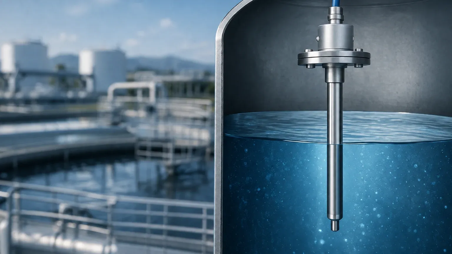
In an industrial tank, the measurement system effectively forms a large capacitor. The sensing probe (electrode) acts as one plate, and the tank wall (if metal) acts as the second plate. If the tank is non-conductive (e.g., plastic or fiberglass), a secondary reference ground rod is installed to serve as the second plate. The material being measured—whether it is water, oil, or a chemical solvent—acts as the dielectric medium.
The Capacitance Formula
The capacitance is determined by the formula:
$$C = \epsilon_0 \cdot \epsilon_r \cdot \frac{A}{d}$$
Where:
* $C$: Capacitance.
* $\epsilon_0$: Permittivity of free space.
* $\epsilon_r$: Dielectric constant (relative permittivity) of the material between the plates.
* $A$: Area of the plates.
* $d$: Distance between the plates.
In level measurement, the distance ($d$) and the area ($A$) remain constant once the probe is installed. The variable factor is the total dielectric constant within the tank. As the level of the medium rises, it displaces the air (which has a dielectric constant of approximately 1.0). Since almost all process materials have a higher dielectric constant than air, the total capacitance measured by the electronics increases in direct proportion to the level of the material. The internal circuitry of the Main Page equipment then converts this change in capacitance into a standard linear output signal, such as 4-20mA or a digital communication protocol.
Components of a Capacitance Level Indicator System
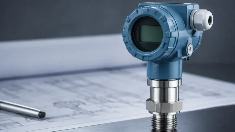
A complete capacitance level indicator system typically consists of three primary components: the probe, the electronic insert (transmitter), and the housing.
1. The Probe (Electrode)
The probe is the part of the instrument that is in direct contact with the process environment. Probes are available in several configurations:
* Rod Probes: Rigid metal rods used for shorter distances, typically up to 3 meters (approx. 10 feet).
* Cable Probes: Flexible stainless steel cables used for tall silos or deep tanks, reaching lengths of 20 meters (approx. 65 feet) or more.
* Insulated Probes: Usually coated with PTFE (Teflon) or PFA. Insulation is mandatory when measuring conductive liquids (like water or acids) to prevent a short circuit between the probe and the tank wall.
* Non-Insulated Probes: Bare metal probes used only for non-conductive materials like oils or dry bulk solids.
2. Electronic Insert
The electronics generate a high-frequency radio frequency (RF) signal that is applied to the probe. The circuitry measures the resulting impedance and extracts the capacitive component. Modern units often feature "Active Shield" technology, which helps the sensor ignore the effects of material build-up on the probe, a common issue in sticky or viscous applications.
3. Housing and Process Connection
The housing protects the electronics from environmental factors (IP65/IP67 ratings). Process connections vary based on the pressure and temperature requirements, ranging from standard NPT/G threads to large industrial flanges.
Industrial Applications and Medium Compatibility
Capacitance level indicators are versatile but require careful matching to the dielectric constant ($\epsilon_r$) of the medium. If the dielectric constant of a material is too low (typically below 1.5 to 2.0), the change in capacitance may be too small for the electronics to detect reliably.
Common Applications
* Water and Wastewater: Monitoring levels in treatment tanks and sumps. Since water is conductive ($\epsilon_r \approx 80$), insulated probes are used.
* Chemical Processing: Measuring corrosive acids and alkalis in storage tanks. The chemical resistance of PTFE-coated probes makes capacitance a preferred choice here.
* Oil and Gas: Interface measurement between oil and water. Because oil and water have vastly different dielectric constants, capacitance sensors can accurately detect the boundary layer between the two liquids.
* Food and Beverage: Monitoring silos containing grains, flour, or sugar. The sensors must be configured to handle the dust and low moisture content of these solids.
| Material | Dielectric Constant ($\epsilon_r$) | Probe Requirement |
| :— | :— | :— |
| Vacuum / Air | 1.0 | N/A |
| Mineral Oil | 2.0 – 2.2 | Non-insulated (Bare) |
| Plastic Pellets | 2.0 – 3.0 | Non-insulated (Bare) |
| Grain / Corn | 3.0 – 5.0 | Non-insulated (Bare) |
| Alcohol | 15 – 25 | Insulated (PTFE/PFA) |
| Water | 80 | Insulated (PTFE/PFA) |
Technical Selection and Specification Guide
When selecting a capacitance level indicator for a specific project, engineers must evaluate several environmental and physical factors to ensure long-term accuracy.
1. Conductivity of the Medium
This is the first decision point. If the medium is conductive (conductivity > 100 $\mu$S/cm), an insulated probe is required. For non-conductive media (like pure oils), a bare probe is often more cost-effective and sensitive.
2. Vessel Material and Geometry
In a metal tank, the wall serves as the ground reference. In a plastic or concrete tank, a "concentric shield" probe or a twin-rod probe must be used to provide a consistent reference ground. Without a stable ground, the capacitance reading will drift or become erratic.
3. Temperature and Pressure
Standard capacitance probes can handle temperatures from -40°C to 200°C (-40°F to 392°F). High-temperature versions with ceramic insulators can extend this range significantly. Pressure ratings must also be verified, especially for boiler or pressurized reactor applications.
4. Continuous vs. Point Level
* Continuous Indicators: Provide a real-time percentage of the tank level (e.g., 0-100%).
* Capacitance Switches: Act as high or low-level alarms, triggering a relay when the material reaches the probe tip.
Installation Best Practices for Reliable Measurement
Proper installation is critical for the performance of a capacitance level indicator. Incorrect placement can lead to interference or mechanical damage.
* Avoid the Inflow Stream: Never install the probe directly under the material inlet. The falling stream will cause false readings and may physically damage the probe over time.
* Clearance from Walls: Maintain a minimum distance from the tank wall (typically at least 100mm or 4 inches) to prevent interference, unless the probe is specifically designed for close-wall mounting.
* Avoid Agitators: Ensure the probe is positioned away from the sweep of any internal mixers or agitators. In some cases, a stilling well (a pipe surrounding the probe) is used to protect the sensor from turbulence.
* Grounding: Ensure a low-resistance electrical connection between the sensor housing and the metal tank. For non-metal tanks, ensure the reference ground rod is properly submerged and connected to the electronics.
* Cable Tension: For cable-type probes used in solids, the downward pull of the material (tensile load) must be calculated to ensure the cable does not snap or pull the mounting flange out of the tank roof.
Limitations and Mitigation Strategies
While highly effective, capacitance technology has specific limitations that must be managed through engineering design.
1. Material Build-up: If a conductive material coats the probe (e.g., sticky sludge), the sensor may continue to read a high level even after the tank is empty.
* *Mitigation:* Use "Active Shield" or "Guard" electronics that ignore the capacitance of the coating.
2. Changes in Dielectric Constant: If the composition of the liquid changes (e.g., switching from one chemical to another with a different $\epsilon_r$), the indicator will require re-calibration.
* *Mitigation:* Use capacitance only for processes where the medium remains consistent, or utilize a compensation probe.
3. Moisture in Solids: In dry bulk applications, a small change in moisture content can significantly change the dielectric constant of the material.
* *Mitigation:* Ensure the material is stored in a controlled environment or use radar-based level meters if moisture fluctuates wildly.
Frequently Asked Questions (FAQ)
Q: Can a capacitance level indicator be used for liquids and solids?
A: Yes, it is one of the few technologies that works effectively for both liquids (water, oils, chemicals) and solids (powders, grains, plastic pellets).
Q: How often does a capacitance probe need calibration?
A: Typically, calibration is performed during commissioning. Unless the dielectric properties of the material change or the probe is physically damaged, the sensor should remain stable for years. Modern digital transmitters allow for easy zero and span adjustment via push-buttons or software.
Q: What is the difference between RF Admittance and Capacitance?
A: RF Admittance is an advanced version of capacitance technology. It measures both the capacitive and resistive components of the electrical signal. This allows the sensor to better distinguish between the actual level and material build-up on the probe.
Q: Is it possible to cut a capacitance probe to length in the field?
A: Some rod and cable probes are designed to be field-cuttable. However, insulated probes (PTFE/PFA) generally cannot be cut without specialized tools to reseal the insulation, as any exposed metal in a conductive liquid will cause measurement failure.
For engineers seeking reliable, cost-effective solutions for industrial level measurement, the capacitance level indicator offers a proven track record. By following the selection and installation guidelines outlined above, users can achieve high-precision monitoring even in challenging process environments. For more information on specific product specifications and application support, visit the Main Page of our technical resource center.