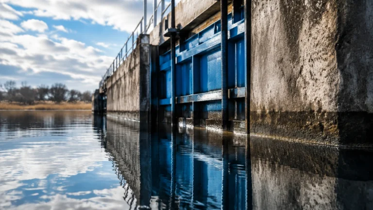
Gauging Station
Gauging Station
A gauging station is a specialized facility used by hydrologists, environmental engineers, and water resource managers to monitor and record the characteristics of terrestrial bodies of water. The primary function of these stations is to measure the water level, also known as "stage," and often to calculate the volumetric flow rate (discharge). In modern industrial and environmental applications, the accuracy of a gauging station depends heavily on the integration of advanced level measurement technologies and robust data acquisition systems.
For professional engineers and project managers, selecting the right instrumentation for a gauging station is a critical decision that impacts the reliability of flood warnings, irrigation management, and environmental impact assessments. This guide explores the technical principles, selection criteria, and installation requirements for the instrumentation that powers modern gauging stations.
Core Measurement Principles in Gauging Stations
Before selecting hardware, it is essential to understand the physical principles used to detect water levels in open channels, rivers, and reservoirs. Most modern gauging stations utilize one of three primary technologies: radar, ultrasonic, or hydrostatic pressure measurement.
1. Radar Level Measurement (Non-Contact)
Radar level meters operate on the Time-of-Flight (ToF) principle. The sensor emits a high-frequency microwave signal (typically in the 26GHz or 80GHz range) toward the water surface. The signal reflects off the water and returns to the sensor. By measuring the time interval between transmission and reception, the device calculates the distance to the water surface.
* Advantages: Radar is unaffected by air temperature, wind, or humidity. It provides high precision (often within ±2 mm) and is ideal for gauging stations located on bridges or high-clearance structures.
* Limitations: Requires a clear line of sight and a minimum dielectric constant of the target medium (though water is an excellent reflector).
2. Ultrasonic Level Measurement (Non-Contact)
Similar to radar, ultrasonic sensors use the ToF principle but employ sound waves instead of microwaves. The sensor emits an ultrasonic pulse that bounces off the water surface.
* Advantages: Highly cost-effective and suitable for smaller gauging stations in calm environments like irrigation canals or small streams.
* Limitations: Sound speed is affected by air temperature gradients, wind, and heavy fog. Integrated temperature compensation is required, but accuracy may still fluctuate in extreme weather conditions.
3. Hydrostatic Pressure Measurement (Contact)
Hydrostatic transmitters are submerged at the bottom of the water body. They measure the pressure exerted by the water column above the sensor. Based on the formula $P = \rho gh$ (where $P$ is pressure, $\rho$ is density, $g$ is gravity, and $h$ is height), the water level is derived.
* Advantages: Unaffected by surface foam, debris, or bridge height. Ideal for deep reservoirs or areas where mounting structures are unavailable.
* Limitations: Requires a vent tube to compensate for atmospheric pressure changes. The sensor is susceptible to silting and physical damage from underwater debris.
Key Components of a Modern Gauging Station
A fully functional gauging station is an ecosystem of hardware and software components designed to operate autonomously in often remote locations. For a comprehensive look at available sensor technologies, engineers often refer to the Main Page of specialized manufacturers to compare technical specifications.
1. Level Sensor: The primary instrument (Radar, Ultrasonic, or Hydrostatic) providing the raw stage data.
2. Data Logger: An industrial-grade computer that records measurements at set intervals (e.g., every 15 minutes). It often performs local calculations, such as converting stage to discharge using a pre-programmed rating curve.
3. Telemetry System: Communication hardware (GPRS/4G/5G, Satellite, or Radio) that transmits data from the remote site to a central monitoring office.
4. Power Supply: Most remote stations rely on a 12V or 24V DC system powered by solar panels and deep-cycle lead-acid or lithium-ion batteries.
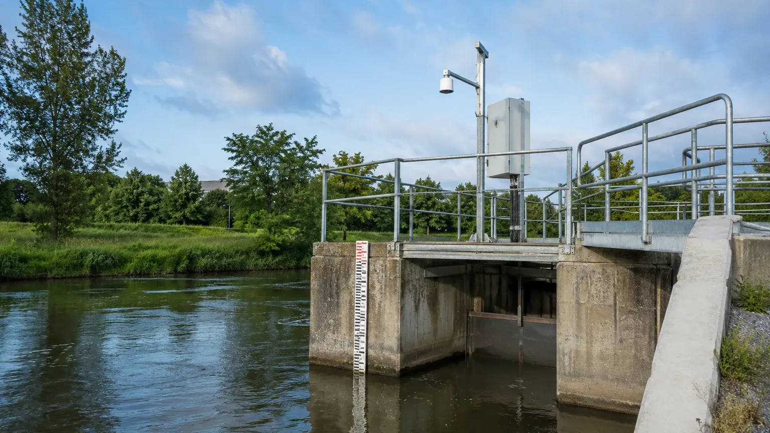
5. Physical Infrastructure: This includes the mounting arm for non-contact sensors, a stilling well (to dampen wave action), and a protective enclosure for the electronics.
Selection Criteria for Gauging Station Sensors
Choosing the correct sensor requires an analysis of the site-specific environmental conditions. The following table provides a comparison for engineering selection.
| Feature | Radar (80GHz) | Ultrasonic | Hydrostatic |
| :— | :— | :— | :— |
| Measurement Range | Up to 35m (standard) | Up to 15m | Up to 200m |
| Accuracy | ±2 mm | ±0.25% of range | ±0.1% to 0.5% of range |
| Installation | Top-down (Non-contact) | Top-down (Non-contact) | Submerged (Contact) |
| Maintenance | Very Low | Low | Moderate (Cleaning required) |
| Environmental Sensitivity | None | High (Wind/Temp) | High (Silt/Ice) |
| Typical Application | Large rivers, flood monitoring | Irrigation, small canals | Reservoirs, deep wells |
Installation Considerations and Best Practices
Proper installation is as important as the quality of the instrument itself. Incorrect mounting can lead to signal loss or inaccurate data that compromises the utility of the gauging station.
Mounting Geometry
For radar and ultrasonic sensors, the beam must be perpendicular to the water surface. Even a small tilt can reduce the returned signal strength. Furthermore, the "beam angle" must be considered; the sensor should be placed far enough from the riverbank or bridge piers to avoid false reflections (ghost echoes).
Stilling Wells
In turbulent waters or high-flow rivers, a stilling well is often used. This is a vertical pipe or chamber connected to the main body of water. It dampens the waves and surface turbulence, providing a calm surface for the sensor to measure. This is particularly useful for hydrostatic sensors to prevent "noise" in the pressure readings caused by rapid flow velocity (Bernoulli effect).
Atmospheric Compensation
For hydrostatic sensors, the cable must include a capillary tube that allows the internal side of the pressure diaphragm to be exposed to atmospheric pressure. If this tube becomes blocked or kinked, the level reading will drift as the local weather changes.
Limitations and Challenges
While modern gauging stations are highly reliable, they are not without challenges:
* Sedimentation: In rivers with high sediment loads, hydrostatic sensors can become buried in silt, leading to inaccurate readings or sensor failure.
* Ice Formation: During winter, ice can form on the water surface. Non-contact sensors will measure the top of the ice, not the water level. Hydrostatic sensors are safer from surface ice but can be damaged if the water freezes solid at the sensor depth.
* Debris: Floating debris, such as logs or vegetation, can damage submerged sensors or cause momentary spikes in non-contact sensor data.
* Vandalism and Wildlife: Remote stations are targets for theft or damage by animals. Using armored cables and secure, inconspicuous enclosures is standard practice.
The Role of the Stage-Discharge Relationship
Most gauging stations are ultimately intended to measure flow (discharge), not just level. This is achieved through a "Rating Curve." Hydrologists perform manual flow measurements at various water levels using current meters or Acoustic Doppler Current Profilers (ADCP). These data points are used to create a mathematical relationship between the measured stage and the actual volume of water moving past the station (measured in $m^3/s$ or $ft^3/s$). Once the rating curve is established, the gauging station's data logger can provide real-time flow data based solely on the level sensor's input.
Frequently Asked Questions (FAQ)
How often should a gauging station be calibrated?
Field calibration should be checked at least twice a year. This involves comparing the sensor's reading against a physical reference, such as a manual staff gauge (a large ruler fixed in the water).
Can radar sensors work under bridges?
Yes, radar sensors are frequently mounted to bridge girders. However, the engineer must ensure the sensor is positioned to avoid detecting the bridge's own structural elements within its beam path.
What is the advantage of 80GHz radar over 26GHz for gauging stations?
80GHz radar has a much narrower beam angle (typically 3° to 4°) compared to 26GHz (typically 8° to 10°). This allows the 80GHz sensor to be used in tighter spaces, such as narrow manholes or near bridge piers, without interference from side reflections.
How is data transmitted from remote gauging stations?
Most modern stations use cellular telemetry (4G/LTE). In areas without cellular coverage, satellite modems (such as Iridium) are used, though they have higher operational costs. For short distances, LoRaWAN or radio telemetry may be appropriate.
Conclusion
A robust gauging station is the backbone of modern water management. By understanding the strengths and limitations of radar, ultrasonic, and hydrostatic technologies, engineers can design monitoring systems that withstand environmental rigors while providing the high-precision data required for safety and resource planning. For those seeking specific hardware configurations and technical support for industrial-grade sensors, visiting the Main Page of a dedicated manufacturer provides the necessary resources to move from the planning phase to implementation.