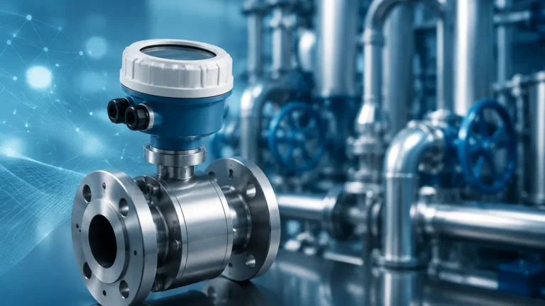
Basınc Sensoru
Basınc Sensoru
In the field of industrial automation and process control, the accurate measurement of liquid levels is often achieved through the application of pressure-sensing technology. A pressure sensor, or *basınc sensoru*, serves as a critical component in hydrostatic level measurement systems. By measuring the force exerted by a liquid column at a specific point, these instruments allow engineers to calculate the height, volume, and mass of fluids within tanks, reservoirs, and open channels. As a professional manufacturer, Welk provides a range of measurement solutions that leverage these principles to ensure reliability in demanding environments such as water treatment, chemical processing, and oil and gas operations.
Understanding the technical nuances of a *basınc sensoru* is essential for selecting the correct instrument for a specific application. This guide explores the underlying physics, the various types of sensors available, and the practical considerations required for successful industrial integration.
The Principle of Hydrostatic Level Measurement
Before selecting a *basınc sensoru*, it is vital to understand the physical principle it employs. Hydrostatic level measurement is based on the relationship between the height of a liquid column and the pressure it exerts at the base of a vessel. This is governed by the hydrostatic pressure formula:
P = ρ × g × h
Where:
* P is the hydrostatic pressure (measured by the sensor).
* ρ (rho) is the density of the liquid.
* g is the acceleration due to gravity (approximately 9.81 m/s²).
* h is the height of the liquid column above the sensor.
In a vented tank or an open body of water, the sensor measures the "gauge pressure," which is the pressure of the liquid minus the ambient atmospheric pressure. Because gravity is constant and the density of many liquids (like water) remains relatively stable, the pressure measured by the *basınc sensoru* is directly proportional to the liquid level. For example, a water column of 10 meters exerts approximately 1 bar (14.5 psi) of pressure. By calibrating the sensor to these parameters, operators can achieve precise real-time level monitoring.
Types of Basınc Sensoru for Level Applications
Industrial pressure sensors are categorized based on their installation method and the type of pressure they measure. Choosing the right configuration is the first step in ensuring long-term accuracy.
1. Submersible Pressure Transmitters
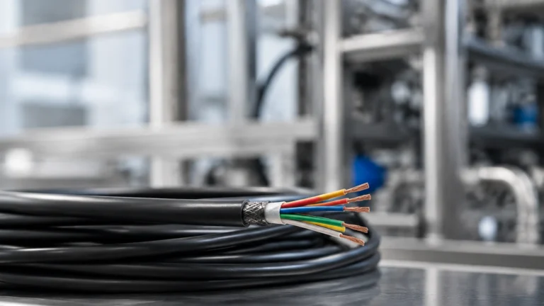
Often referred to as level probes, these sensors are designed to be lowered directly into the medium. They are housed in a waterproof (typically IP68) casing, usually made of stainless steel. A specialized cable contains a vent tube that allows the sensor to reference atmospheric pressure, ensuring that changes in weather or altitude do not affect the level reading. These are ideal for deep wells, boreholes, and large reservoirs.
2. Externally Mounted Pressure Transmitters
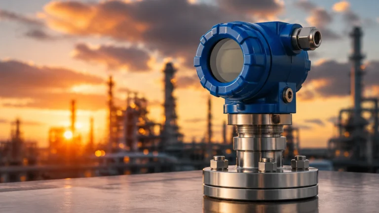
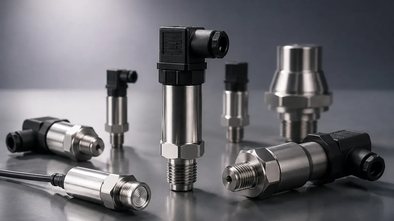
For tanks where the sensor cannot be submerged, an external *basınc sensoru* is mounted to a process connection (threaded or flanged) at the bottom or side of the vessel. This type is common in chemical and food processing where the sensor must be easily accessible for cleaning or maintenance without emptying the tank.
3. Differential Pressure (DP) Transmitters
In pressurized or closed tanks, a single pressure sensor cannot accurately measure level because the gas pressure above the liquid adds to the total pressure at the bottom. A differential pressure transmitter uses two sensing elements—one at the bottom and one at the top (gas phase). The instrument subtracts the top pressure from the bottom pressure, leaving only the hydrostatic pressure of the liquid column. This is a standard requirement in boiler drum level and liquefied gas storage.
Technical Selection Criteria
Selecting a *basınc sensoru* requires a detailed analysis of the process conditions. Failure to account for media characteristics or environmental factors can lead to premature sensor failure or measurement drift.
* Pressure Range: The sensor must be rated for the maximum possible head pressure. It is standard practice to select a sensor with a range slightly higher than the maximum expected level to prevent damage from pressure spikes.
* Material Compatibility: The wetted parts—the diaphragm and the housing—must resist corrosion. While 316L stainless steel is standard, aggressive chemicals may require ceramic diaphragms or exotic alloys like Hastelloy or Tantalum.
* Accuracy and Stability: Industrial applications typically require accuracy within 0.1% to 0.5% of the full scale. Long-term stability is also crucial to minimize the frequency of recalibration.
* Output Signals: Most modern systems utilize a 4-20mA analog signal, often paired with the HART protocol for digital communication and remote diagnostics. For integrated automation, Modbus RTU or Profibus options may be necessary.
Comparison Table: Choosing the Right Sensor Technology
The following table provides a quick reference for comparing different *basınc sensoru* configurations based on typical application needs.
| Feature | Submersible Probe | External Threaded/Flanged | Differential Pressure (DP) |
| :— | :— | :— | :— |
| Best Use Case | Deep wells, open tanks | Process tanks, chemicals | Pressurized/Closed vessels |
| Installation | Suspended by cable | Mounted to pipe/vessel wall | Dual-port connection |
| Maintenance | Requires pulling from liquid | Accessible from outside | Complex piping/valves |
| Atmospheric Venting | Via cable vent tube | Internal or external vent | Not required (differential) |
| Media Constraints | Non-clogging fluids | Wide range of viscosities | Clean liquids/gases |
Installation Considerations and Best Practices
Correct installation is as important as the sensor's technical specifications. Even the highest quality *basınc sensoru* will provide inaccurate data if installed poorly.
1. Positioning: The sensor should be located away from areas of high turbulence, such as pump inlets or agitator blades. If turbulence is unavoidable, a stilling well (a perforated pipe) should be used to protect the sensor and provide a stable measurement environment.
2. Venting: For gauge pressure sensors, the vent tube must remain clear of obstructions. Moisture entering the vent tube can cause measurement errors or internal corrosion. Using a desiccant filter at the end of the vent tube is highly recommended in humid environments.
3. Protection from Debris: In wastewater or untreated water applications, silt and debris can accumulate around the diaphragm. Periodic cleaning or the use of a flush-diaphragm design can prevent build-up that might dampen the pressure signal.
4. Cable Integrity: For submersible units, the cable should be secured with a proper suspension clamp to prevent stretching, which could damage the internal vent tube or wiring.
Limitations and Operating Constraints
While hydrostatic pressure measurement is a robust and cost-effective method, it has specific limitations that engineers must manage:
* Density Sensitivity: Since the level calculation relies on the density of the liquid (ρ), any change in density will result in a measurement error. For example, if the temperature of a liquid increases, its density typically decreases. The *basınc sensoru* will detect lower pressure even if the physical level remains the same. In such cases, temperature compensation or a secondary density measurement is required.
* Viscosity: Highly viscous fluids or those that tend to solidify can coat the diaphragm, leading to sluggish response times or total sensor blockage.
* Mechanical Stress: Pressure sensors are sensitive to "water hammer"—sudden pressure surges caused by valves closing rapidly. Installing snubbers or choosing sensors with high overpressure ratings can mitigate this risk.
Frequently Asked Questions (FAQ)
Q: How often should a basınc sensoru be calibrated?
A: Calibration frequency depends on the application's criticality and the environment. For most industrial processes, an annual check is sufficient. However, in harsh chemical environments, semi-annual calibration may be necessary to account for potential diaphragm drift.
Q: Can a pressure sensor measure the level of solids?
A: Generally, no. Hydrostatic pressure measurement relies on the fluid properties of liquids to exert equal pressure in all directions. Solids do not behave this way and cannot be accurately measured using standard hydrostatic principles.
Q: What is the difference between a pressure transmitter and a pressure transducer?
A: While the terms are often used interchangeably, a transducer typically refers to a device that converts pressure into a low-level voltage signal (e.g., 0-100mV), while a transmitter converts it into a standardized industrial signal like 4-20mA, which can be transmitted over long distances without signal loss.
Q: How do I protect the sensor from lightning or electrical surges?
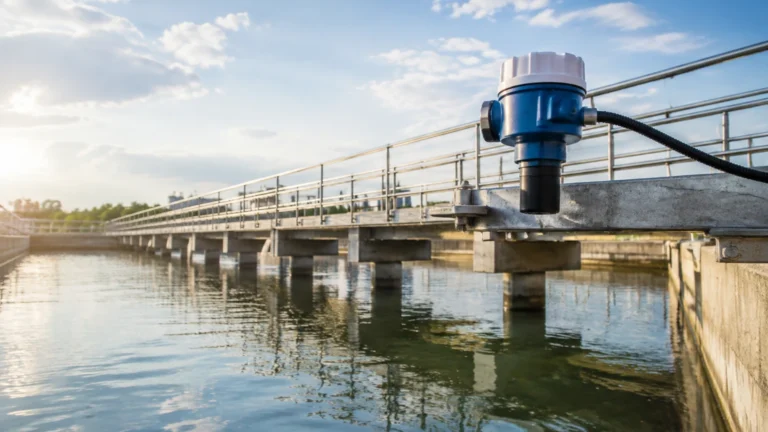
A: Many high-quality industrial sensors include internal surge protection. However, for outdoor installations (like reservoirs), additional external surge arrestors on the signal line are recommended to protect the PLC or control system.
Conclusion
The *basınc sensoru* remains a cornerstone of industrial level measurement due to its simplicity, reliability, and versatility. By understanding the hydrostatic principles and carefully evaluating the specific needs of your process—from material compatibility to installation environment—you can ensure an accurate and long-lasting measurement solution. For more detailed technical specifications and to explore our full range of industrial level measurement instruments, please visit our Main Page for comprehensive product options and application support.