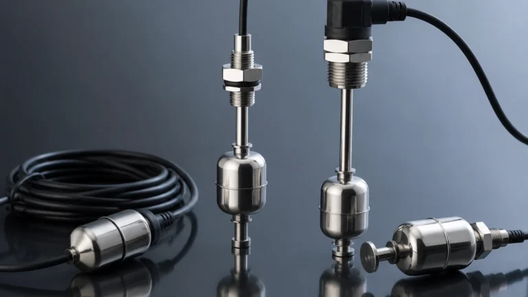
Capacitive Probe
Capacitive Probe
In the landscape of industrial level measurement, the capacitive probe remains one of the most versatile and robust technologies available to process engineers. Whether used for point level detection or continuous level monitoring, capacitive technology leverages the electrical properties of the stored material to provide real-time data. As a professional manufacturer, Welk provides high-precision capacitive solutions designed to withstand the rigors of chemical processing, water treatment, and oil and gas operations. This guide explores the engineering principles, selection criteria, and installation requirements for capacitive probes in modern industrial environments.
Understanding the Capacitive Measurement Principle
The fundamental operation of a capacitive probe is based on the electrical principle of a capacitor. In a standard electronic circuit, a capacitor consists of two conductive plates separated by an insulating material known as a dielectric. The ability of this setup to store an electrical charge is defined as capacitance, measured in Farads (typically picofarads or pF in level sensing).
In an industrial tank application, the capacitive probe acts as one plate of the capacitor, while the vessel wall (if conductive) acts as the second plate. The space between them contains the medium being measured (the dielectric). The total capacitance is governed by the formula:
C = ε × (A / d)
Where:
- C is the capacitance.
- ε (Epsilon) is the dielectric constant of the material between the plates.
- A is the surface area of the plates.
- d is the distance between the plates.
In level measurement, the area (A) and the distance (d) remain constant once the probe is installed. Therefore, the capacitance becomes directly proportional to the dielectric constant (ε) of the material in the tank. Since most process materials have a significantly higher dielectric constant than air (εr ≈ 1), the total capacitance increases as the material rises and covers more of the probe. The electronics in the probe head convert this change in capacitance into a linear 4-20mA signal or a switching output.
Key Components of a Capacitive Probe System
A complete capacitive level sensing system generally consists of three primary elements:
1. The Probe (Electrode): This is the sensing element that extends into the vessel. It can be a rigid rod for shorter distances or a flexible cable for deep silos. Depending on the conductivity of the medium, the probe may be bare metal or insulated with a polymer like PTFE or PFA.
2. The Electronic Insert: Located in the housing at the top of the probe, this circuitry generates the high-frequency signal used to measure capacitance and processes the return signal into a usable industrial output.
3. The Reference (Ground): For the circuit to be complete, a second conductive surface is required. In metal tanks, the tank wall serves as the ground. In non-conductive tanks (such as plastic or fiberglass), a secondary ground rod or a concentric shield is integrated into the probe design.
Types of Capacitive Probes and Their Applications
Selecting the correct probe geometry is essential for measurement accuracy. Capacitive probes are generally categorized by their mechanical construction and their intended use (point level vs. continuous level).
Rod Probes
Rod probes are rigid electrodes typically used in smaller vessels or for point level detection. They are highly durable and can withstand mechanical stress from agitated liquids. Welk rod probes are often used in chemical dosing tanks where precision is required over a range of 0.5 to 4 meters.
Cable Probes
For deep tanks, wells, or large solids silos, rigid rods are impractical due to shipping and installation constraints. Cable probes utilize a weighted flexible stainless steel cable, allowing for measurements up to 30 meters (approx. 98 feet) or more. These are common in the grain and mining industries for monitoring bulk solids.
Insulated vs. Non-Insulated Probes
- Insulated Probes: These are coated with a dielectric material (like PTFE). They are mandatory for conductive liquids (such as water or acids) to prevent a short circuit between the probe and the liquid.
- Non-Insulated Probes: These bare metal probes are used for non-conductive materials like oils, hydrocarbons, or dry powders. They are generally more cost-effective but limited in application scope.
Engineering Selection Criteria for Capacitive Probes
To ensure reliable performance, engineers must evaluate several environmental and material factors before specifying a capacitive probe. For a comprehensive overview of available technologies, engineers can visit the Main Page of our product catalog.
Dielectric Constant (εr)
The dielectric constant of the medium is the most critical factor. Materials with a high εr (e.g., water, εr ≈ 80) are very easy to measure. Materials with a low εr (e.g., plastic pellets or dry oils, εr ≈ 1.5 to 2.5) require more sensitive electronics and potentially a larger probe surface area to generate a detectable change in capacitance.
Vessel Material
If the vessel is made of metal, it acts as the ground reference. If the vessel is non-conductive (plastic, glass, or lined), a "dual-pole" probe or a probe with a ground tube must be used to provide a stable reference point for the capacitance field.
Temperature and Pressure
Industrial processes often involve extreme conditions. Capacitive probes are favored in high-temperature applications where ultrasonic or radar sensors might fail due to vapor or foam. Standard probes can handle temperatures up to 200°C, with specialized high-temperature versions reaching much higher.
Selection Summary Table
| Feature | Rod Probe | Cable Probe | Concentric Shield Probe |
| :— | :— | :— | :— |
| Max Length | 3 – 6 meters | 30+ meters | 3 meters |
| Best For | Liquids, small tanks | Solids, deep silos | Low dielectric liquids |
| Agitation Resistance | High | Low (requires anchoring) | Very High |
| Installation | Top or Side | Top only | Top only |

Installation Best Practices and Configuration
Proper installation is the difference between a reliable instrument and a source of constant maintenance. When installing a capacitive probe, follow these engineering guidelines:
1. Avoid the Fill Stream: Never install a probe directly in the path of the incoming material. The falling product will cause erratic readings and can physically damage the probe over time.
2. Maintain Distance from Walls: To prevent interference, the probe should be installed at a specific distance from the tank wall (typically at least 100mm to 200mm), unless the wall is intended to be the ground reference.
3. Grounding Continuity: Ensure there is a low-resistance electrical connection between the probe housing and the metal tank. Use conductive thread sealant or a dedicated grounding strap if the tank is painted or coated.
4. Dead Zones: Be aware of the "inactive length" at the top of the probe. This is the portion of the probe that does not measure level, usually near the mounting thread, to prevent false triggers from the tank nozzle.
Limitations and Maintenance Considerations
While highly versatile, capacitive probes are not "fit and forget" in every application. Engineers should be aware of the following challenges:
* Material Buildup (Coating): Conductive materials that stick to the probe (like thick slurries or wastewater) can create a "bridge" to the tank wall, leading the sensor to report a full tank even when it is empty. Modern Welk probes utilize "active shield" technology to ignore the effects of coating.
* Changing Dielectric Constants: If the process involves mixing different fluids with significantly different dielectric constants, the calibration will shift. Capacitive probes are best suited for processes where the material composition remains relatively consistent.
* Moisture Content: In solids measurement, a change in the moisture content of the material can drastically alter its dielectric constant, leading to measurement errors.
Frequently Asked Questions (FAQ)
Q: Can a capacitive probe be used in a plastic tank?
A: Yes, but you must use a probe with a reference electrode (ground rod) or a concentric shield. Since the plastic wall cannot act as a ground, the probe needs its own internal ground to complete the circuit.
Q: How do I calibrate a capacitive probe?
A: Most modern probes feature a "two-point calibration." You calibrate the "zero" or 4mA point when the tank is empty and the "full" or 20mA point when the tank is at its maximum level. Some smart probes allow for dry calibration if the dielectric constant of the material is known.
Q: Is a capacitive probe affected by foam?
A: Capacitive probes are generally less affected by foam than ultrasonic sensors. However, depending on the conductivity and density of the foam, it may be detected as a level. If foam should be ignored, the sensitivity of the probe must be adjusted during commissioning.
Q: What is the difference between a capacitive probe and a tuning fork switch?
A: A capacitive probe measures the electrical property (capacitance) of the medium, while a tuning fork measures mechanical vibration damping. Capacitive probes are better for continuous level measurement, while tuning forks are strictly for point level detection.
Conclusion
The capacitive probe remains a cornerstone of industrial automation due to its lack of moving parts, high pressure/temperature resistance, and adaptability to various media. By understanding the dielectric properties of the process material and selecting the appropriate probe geometry, facilities can achieve highly accurate level monitoring. For technical assistance in selecting the right instrument for your specific application, please refer to the technical resources available on our Main Page. Welk continues to innovate in the field of level measurement, providing the reliable data necessary for safe and efficient industrial operations.