Carbon Capture Monitoring
Carbon Capture Monitoring
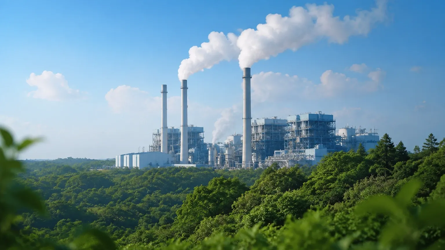
Carbon Capture, Utilization, and Storage (CCUS) has transitioned from a specialized environmental concept to a critical industrial requirement. As global industries strive to meet decarbonization targets, the technical demand for precise carbon capture monitoring has intensified. This process involves capturing carbon dioxide (CO2) from industrial sources, such as power plants or chemical facilities, and either reusing it or storing it underground to prevent its release into the atmosphere.
Effective monitoring in these systems is not merely about environmental compliance; it is fundamental to process safety, efficiency, and the integrity of the storage infrastructure. Within a CCUS plant, level measurement plays a pivotal role in managing the solvents used for capture, the separation of gases, and the storage of liquefied CO2. This guide provides a technical overview of the technologies, selection criteria, and practical considerations for implementing level measurement solutions in carbon capture applications.
Understanding Carbon Capture Monitoring in Industrial Processes
Carbon capture monitoring encompasses the tracking of CO2 throughout its lifecycle: capture, transport, and storage. In the capture phase, chemical solvents (often amines) absorb CO2 from flue gas. These solvents are then heated in a stripper to release pure CO2. In these stages, monitoring the levels in absorption towers and flash tanks is essential to prevent overflow and ensure optimal gas-liquid contact.
Once captured, the CO2 is compressed into a liquid or supercritical state for transport via pipelines or ships. Monitoring the level in high-pressure storage tanks and surge vessels is critical to managing inventory and ensuring the stability of the transport chain. For engineers and plant managers, selecting the right instrumentation requires a deep understanding of the physical properties of CO2 and the chemical nature of the solvents involved.
Core Measurement Principles for CCUS Level Monitoring
Before selecting an instrument, it is vital to understand the physical principles that govern level measurement in these environments. Each technology interacts differently with the process media.
Radar Level Measurement (Non-Contact and Guided Wave)
Radar technology operates on the Time-of-Flight (ToF) principle. A sensor emits high-frequency microwave pulses that travel to the surface of the medium and reflect back. The distance is calculated based on the time taken for the pulse to return.
- Non-Contact Radar: Ideal for corrosive solvents as the sensor does not touch the liquid. It is highly accurate and unaffected by pressure or temperature changes.
- Guided Wave Radar (GWR): Uses a probe to guide the microwave signal. This is particularly effective in low-dielectric media like liquid CO2, where a stronger reflection is required.
Hydrostatic Level Measurement
This principle relies on the relationship between liquid height and pressure ($P = \rho \cdot g \cdot h$). A pressure transmitter at the bottom of the tank measures the head pressure exerted by the liquid column. While reliable, this method requires accurate knowledge of the fluid's density, which can fluctuate significantly with temperature in CO2 applications.
Ultrasonic Level Measurement
Similar to radar, ultrasonic sensors use sound waves. However, because sound requires a medium to travel, its speed is influenced by the composition and temperature of the gas space above the liquid. In carbon capture monitoring, where the gas space is often pure CO2 or a complex mixture, ultrasonic sensors require careful calibration or may be limited to atmospheric pressure applications.
Magnetic Level Gauges
These instruments use a float containing a magnet that moves with the liquid level. This magnet interacts with an external indicator or transmitter. This provides a clear visual indication and a secondary electronic signal, which is highly valued for safety-critical storage tanks.
For a comprehensive overview of available technologies and technical support, engineers can visit the Main Page to explore specific instrument specifications and application-ready hardware.
Key Evaluation Criteria for Instrument Selection
Selecting instrumentation for carbon capture monitoring involves navigating high pressures, low temperatures, and chemically aggressive environments. The following criteria are essential for a successful deployment:
1. Media Compatibility: Solvents like Monoethanolamine (MEA) can be corrosive to certain metals and elastomers. Instruments must be constructed from resistant materials such as 316L stainless steel, Hastelloy, or PTFE-lined components.
2. Pressure and Temperature Ratings: CO2 is often stored at high pressures (up to 70 bar or more) and low temperatures (down to -50°C). Instruments must be certified to withstand these extremes without mechanical failure or signal drift.
3. Dielectric Constant (εr): Liquid CO2 has a low dielectric constant (approximately 1.6). This makes it a poor reflector for standard radar. High-sensitivity radar or guided wave radar with coaxial probes are often necessary to ensure a reliable signal.
4. Phase Transition Awareness: CO2 can exist in gas, liquid, or supercritical states. Monitoring systems must be able to handle potential phase changes within the vessel, particularly during filling or venting operations.
Practical Application Scenarios and Selection Tables
Different stages of the CCUS process require different measurement approaches. The table below summarizes the typical technology recommendations based on the application environment.
| Application Stage | Typical Media | Process Conditions | Recommended Technology | Why? |
| :— | :— | :— | :— | :— |
| Absorption Tower | Amine Solvents | Low pressure, 40°C – 60°C | Non-contact Radar | Resists corrosion; ignores foam. |
| Stripper/Regenerator | Amine + Heat | Moderate pressure, >100°C | Guided Wave Radar | Handles steam and turbulence well. |
| CO2 Storage Tank | Liquefied CO2 | High pressure (20+ bar), -20°C | GWR or Magnetic Gauge | Reliable in low-dielectric liquids. |
| Separation Tanks | Water/CO2 Mix | Variable | Hydrostatic Transmitter | Cost-effective for simple water separation. |
| Buffer Tanks | Gaseous/Liquid CO2 | Fluctuating | Ultrasonic (Atmospheric) | Suitable for simple atmospheric monitoring. |
Installation Considerations and Maintenance Guidelines
Correct installation is as critical as instrument selection. In carbon capture monitoring, the physical environment of the tank often dictates the success of the measurement.
Stilling Wells and Bypass Chambers
For liquids with low dielectric constants or high turbulence (like boiling CO2), installing a radar sensor inside a stilling well or a bypass chamber is recommended. This concentrates the signal and eliminates surface agitation, providing a much more stable reading.
Nozzle Placement
Nozzles should be positioned away from the inlet flow to avoid false readings caused by the incoming stream. For non-contact radar, ensure there are no internal obstructions (like ladders or heating coils) within the signal's beam path.
Insulation and Heat Tracing
In liquefied CO2 storage, the tank is typically insulated. The instrument mounting should also be designed to prevent heat ingress, which could cause the CO2 to boil locally around the sensor, creating bubbles that interfere with the measurement.
Maintenance Protocols
- Calibration Checks: Periodic verification against a secondary manual measurement is essential, especially for hydrostatic sensors where density shifts may occur.
- Seal Integrity: Given the high pressures involved, seals and gaskets should be inspected annually for signs of degradation or leaks.
- Cleaning: In solvent-based capture systems, buildup can occur on probes. Choosing sensors with self-cleaning capabilities or non-contact designs reduces maintenance frequency.
Common Risks and Technical Limitations
Engineers must be aware of the specific risks associated with carbon capture monitoring to avoid common pitfalls:
* Foaming: Amine solvents are prone to foaming in the absorption tower. Standard ultrasonic and some radar sensors may struggle to distinguish between the foam and the liquid surface. High-frequency radar (80 GHz) or GWR is generally better at penetrating foam.
* Density Variations: If using hydrostatic transmitters, any change in the temperature of the CO2 will change its density, leading to significant level errors. Multivariable transmitters that compensate for temperature and pressure are required in these instances.
* Supercritical Transitions: Near the critical point of CO2 (31.1°C, 73.8 bar), the distinction between liquid and gas disappears. Level measurement becomes impossible in the supercritical phase, so monitoring systems must be designed for the liquid phase below these limits.
Project Implementation Checklist
Before finalizing a carbon capture monitoring project, the engineering team should confirm the following data points:
- [ ] Fluid Properties: What is the exact chemical composition of the solvent? What is the dielectric constant of the liquid?
- [ ] Operating Range: What are the maximum and minimum operating pressures and temperatures?
- [ ] Tank Geometry: Are there internal obstructions? Is there a bypass chamber available?
- [ ] Output Requirements: Is a 4-20mA signal sufficient, or is a digital protocol like HART, Foundation Fieldbus, or Profibus required for integration into the DCS?
- [ ] Safety Certification: Does the application require SIL (Safety Integrity Level) rated instrumentation for overfill prevention?
Frequently Asked Questions (FAQ)
Q: Why is non-contact radar preferred over ultrasonic for CO2 capture?
A: Ultrasonic waves are affected by the gas composition and pressure. Since carbon capture involves high-pressure CO2 or varying gas mixtures, the speed of sound changes, leading to inaccuracies. Radar uses microwaves, which are largely unaffected by these gas-phase changes.
Q: How does low dielectric constant affect level measurement?
A: A low dielectric constant means the liquid reflects less energy back to the sensor. If the εr is too low (below 1.5), a standard radar signal might pass right through the liquid to the tank bottom. Using guided wave radar with a coaxial probe solves this by concentrating the energy.
Q: Can hydrostatic transmitters be used for refrigerated CO2?
A: Yes, but only if the system can compensate for density. Since the density of liquid CO2 changes significantly with small temperature shifts, a static density calculation will lead to errors. A dual-pressure system (differential pressure) is usually required to account for the vapor pressure in the tank.
Q: What materials are best for amine solvent monitoring?
A: 316L Stainless Steel is the standard. However, for high-temperature stripper applications where the amine is most aggressive, materials like Hastelloy C276 or specific PTFE coatings may be necessary to prevent pitting and stress corrosion cracking.
By following these technical guidelines and selecting the appropriate measurement principle, industrial operators can ensure that their carbon capture monitoring systems provide the reliability and accuracy needed for modern decarbonization efforts.