Carbon Capture Units
Carbon Capture Units
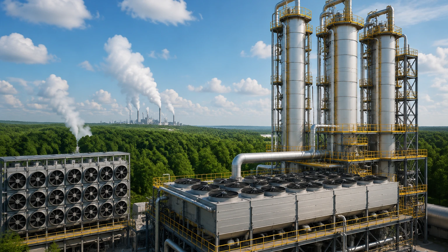
Carbon capture units (CCUs) represent a critical infrastructure component in the global transition toward industrial decarbonization. These systems are designed to intercept carbon dioxide (CO2) emissions from industrial processes—such as power generation, cement manufacturing, and chemical production—before they reach the atmosphere. For engineers and plant operators, managing a carbon capture unit requires precise control over complex chemical and physical phases. Accurate level measurement is fundamental to the efficiency of these units, ensuring that absorption columns, flash tanks, and storage vessels operate within safe and optimal parameters.
In this guide, we examine the technical architecture of carbon capture units, the physical principles of level measurement required for their operation, and the selection criteria for instrumentation in these demanding environments.
Technical Overview of Carbon Capture Units
Carbon capture units typically employ one of three primary technological pathways: post-combustion, pre-combustion, or oxy-fuel combustion. Among these, post-combustion amine scrubbing is the most widely adopted in industrial automation and chemical sectors.
In a standard amine-based carbon capture unit, flue gas enters an absorber column where it contacts a liquid solvent (typically monoethanolamine or MEA). The solvent chemically binds with the CO2. The "rich" solvent is then pumped to a stripper column (or regenerator), where heat is applied to break the chemical bond, releasing pure CO2 for compression and storage while regenerating the "lean" solvent for reuse.
Each stage of this process involves liquid-gas interfaces, pressurized vessels, and corrosive chemical environments. Reliability in these units depends heavily on the ability to monitor solvent levels to prevent pump cavitation, absorber flooding, or dry-running of reboilers.
Level Measurement Principles in Carbon Capture
Before selecting instrumentation for carbon capture units, it is essential to understand the physical principles governing different measurement technologies. Each method interacts differently with the process media, such as aqueous amine solutions or liquefied CO2.
Radar Level Measurement (ToF)
Radar level meters operate on the Time-of-Flight (ToF) principle. The device emits high-frequency electromagnetic pulses (typically in the 26GHz or 80GHz range). These pulses travel at the speed of light, reflect off the surface of the process media, and return to the sensor. The distance is calculated based on the time interval between transmission and reception.
* Non-contact Radar: Ideal for corrosive solvents as the sensor does not touch the liquid. It is unaffected by pressure and temperature changes within the vessel.
* Guided Wave Radar (GWR): Uses a physical probe to guide the signal. This is highly effective in low-dielectric media or applications where foam is present, as the probe concentrates the energy of the pulse.
Ultrasonic Level Sensing
Ultrasonic sensors emit high-frequency sound waves that reflect off the liquid surface. The sensor measures the time taken for the echo to return. While cost-effective, ultrasonic measurement is sensitive to the vapor space composition. In carbon capture units, the presence of heavy CO2 vapors or steam can alter the speed of sound, requiring precise temperature and gas-density compensation.
Hydrostatic Level Transmission
This principle relies on the relationship between liquid height and the pressure exerted at the base of a vessel. The pressure ($P$) is equal to the height ($h$) multiplied by the fluid density ($
ho$) and gravity ($g$). In pressurized carbon capture tanks, a differential pressure (DP) approach is required, where the pressure of the gas blanket is subtracted from the total pressure at the bottom to isolate the liquid level.
Magnetic Level Gauges
Magnetic level gauges utilize a float containing a permanent magnet that moves with the liquid level inside a bypass chamber. This magnet actuates external flags or a transmitter. This is a mechanical, visual solution that provides a robust secondary reference for operators in the field, requiring no power for the visual display.
Selection Criteria for Carbon Capture Applications
Choosing the right instrument for carbon capture units involves evaluating the chemical compatibility, process pressure, and the physical state of the CO2. The following table provides a selection framework for common CCU measurement points.
Selection Table for CCU Instrumentation
| Application Point | Media Type | Recommended Technology | Key Benefit |
| :— | :— | :— | :— |
| Absorber Sump | Amine Solvent (Rich) | Guided Wave Radar | Resists foam interference and turbulence. |
| Stripper Column | Amine Solvent (Lean) | Non-contact Radar (80GHz) | High precision at high temperatures (up to 200°C). |
| CO2 Flash Tank | Liquid/Gaseous CO2 | Differential Pressure | Reliable in high-pressure saturated environments. |
| Reflux Drum | Water/Condensate | Ultrasonic or Radar | Simple installation for stable, low-temp liquids. |
| CO2 Storage Tank | Liquefied CO2 | High-Frequency Radar | Accurate measurement through thick tank walls/insulation. |
| Solvent Storage | Bulk Amine | Hydrostatic | Cost-effective for large atmospheric tanks. |
For a comprehensive overview of available technologies and technical specifications, engineers should Review product options and application support to ensure compliance with specific project requirements.
Installation and Engineering Considerations
Successful deployment of level sensors in carbon capture units requires attention to mechanical and electrical installation details.
1. Nozzle Geometry: For non-contact radar, the nozzle height and diameter must be optimized to prevent signal interference from the nozzle edge. 80GHz radars are generally more forgiving due to their narrow beam angle (often as low as 3°).
2. Stilling Wells and Bypass Chambers: In vessels with significant internal agitation or foam—common in amine absorbers—installing the sensor within a stilling well or a bypass pipe can stabilize the liquid surface and provide a cleaner signal return.
3. Material Compatibility: Amine solvents can be aggressive toward certain elastomers. Sensors should utilize PTFE or PEEK wetted parts, and metallic components should typically be 316L stainless steel or higher alloys like Hastelloy in high-temperature zones.
4. Pressure Compensation: In CO2 liquefaction stages, pressures can exceed 50 bar. Ensure all sensors, especially hydrostatic diaphragms and flange ratings, are specified for the maximum allowable working pressure (MAWP) of the vessel.
Limitations and Operational Risks
While modern level instruments are highly advanced, carbon capture units present specific challenges that can impact performance:
* Foam Formation: Amine solutions are prone to foaming, especially when impurities are present. Foam can absorb radar and ultrasonic signals, leading to "lost echo" errors. Guided wave radar is the most resilient technology in these scenarios.
* Condensation and Buildup: In the stripper column, steam and solvent vapors can condense on sensor faces. Sensors with "drip-off" antenna designs or air purging systems are recommended to prevent signal attenuation.
* Gas Phase Density: At high pressures, the density of gaseous CO2 approaches that of the liquid. This can affect the accuracy of hydrostatic and ultrasonic sensors. Radar is generally immune to these density changes.
Frequently Asked Questions (FAQs)
Q: Why is 80GHz radar preferred over 26GHz for carbon capture units?
A: 80GHz radar offers a much narrower beam, which allows it to avoid internal obstructions like heating coils or ladders in the stripper and absorber columns. It also provides better resolution, which is critical when measuring through heavy vapors.
Q: Can ultrasonic sensors be used in CO2 storage tanks?
A: It is generally not recommended for pressurized CO2 storage. The high concentration of CO2 gas significantly alters the speed of sound compared to air, leading to large measurement errors unless the sensor is specifically calibrated for a 100% CO2 environment.
Q: How do you handle level measurement in a vacuum flasher?
A: Vacuum conditions can cause solvents to boil at lower temperatures, creating surface turbulence. Guided wave radar or differential pressure transmitters with remote seals are the most stable options for vacuum applications.
Q: What maintenance is required for level sensors in amine service?
A: Periodic inspection of wetted parts for signs of chemical degradation or scaling is essential. For non-contact sensors, checking the antenna for crystalline buildup from the solvent is recommended during scheduled shutdowns.
By understanding the specific demands of carbon capture units and applying the correct measurement principles, operators can ensure the long-term reliability and safety of their carbon sequestration and utilization efforts. For further technical data on industrial level measurement, visit the Main Page of our engineering resource.