Open Channel Flow Meters
Open Channel Flow Meters
In industrial water management and municipal infrastructure, measuring the flow of liquids in non-pressurized conduits is a critical requirement. Open channel flow occurs whenever liquid flows in a pipe, culvert, or canal where the top surface is open to the atmosphere. Unlike closed-pipe systems where electromagnetic or vortex meters are common, measuring flow in an open channel requires a different set of physical principles and instrumentation.
Accurate measurement is essential for regulatory compliance in wastewater discharge, billing in irrigation systems, and process control in industrial cooling or treatment plants. This guide examines the principles, technologies, and selection criteria for open channel flow meters, providing an engineering reference for selecting the most appropriate solution for specific site conditions.
Measurement Principles: The Level-to-Flow Relationship
Most open channel flow meters do not measure velocity directly. Instead, they utilize a mathematical relationship between the liquid level (head) and the flow rate. To make this relationship predictable and repeatable, a "primary device" is typically installed in the channel.
Primary Devices: Weirs and Flumes
A primary device is a hydraulic structure that restricts the flow, creating a known relationship between the liquid level upstream of the restriction and the volume of liquid passing through it.
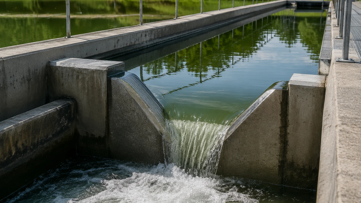
1. Weirs: A weir is essentially a dam or obstruction across the channel. The liquid flows over the top of the weir (the crest). Common types include V-notch weirs (ideal for low flow rates) and rectangular weirs (for higher volumes). The flow rate is calculated based on the height of the liquid above the weir crest.
2. Flumes: A flume is a specially shaped section of the channel that narrows the flow (the throat) and then expands it. Examples include Parshall flumes and Palmer-Bowlus flumes. Flumes are often preferred over weirs because they are self-cleaning and cause less head loss (pressure drop).
The Mathematical Basis
For any given primary device, the flow rate (Q) is expressed as a function of the head (H):
Q = kHⁿ
Where *k* and *n* are constants specific to the dimensions and type of the primary device. The secondary instrument—the open channel flow meter—measures the level (H) and uses an internal microprocessor to calculate the flow rate (Q) in real-time.
Area-Velocity Method
In channels where installing a primary device is impractical (e.g., very large rivers or existing sewers where modifications are restricted), the area-velocity method is used. This requires measuring both the level (to determine the cross-sectional area) and the average velocity of the fluid (often using Doppler ultrasonic or radar velocity sensors).
Core Technologies for Level Measurement
Since most open channel flow systems rely on level measurement, the choice of level sensor is the most critical technical decision. As a manufacturer of industrial measurement instruments, Welk provides several technologies suitable for these applications.
1. Ultrasonic Level Sensors
Ultrasonic sensors are the most common choice for open channel flow. They work by emitting a high-frequency sound pulse that reflects off the liquid surface. The time-of-flight is used to calculate the distance.
* Advantages: Non-contact, relatively low cost, and easy to install.
* Limitations: Performance can be affected by heavy foam, high winds, or significant temperature gradients between the sensor and the liquid surface, as the speed of sound varies with air temperature.
2. Radar Level Meters
Radar technology, particularly 80GHz high-frequency radar, has become increasingly popular for open channel applications. Radar emits electromagnetic waves rather than sound waves.
* Advantages: Unaffected by air temperature, wind, vapors, or dust. They provide higher precision (often ±2mm) and are better suited for outdoor installations where environmental conditions vary.
* Limitations: Higher initial capital cost compared to basic ultrasonic units.
3. Hydrostatic Level Transmitters
These are contact-based sensors that measure the pressure exerted by the liquid column. The pressure is directly proportional to the depth of the liquid.
* Advantages: Ideal for applications where the surface is covered in thick foam (which might scatter ultrasonic or radar signals) or where there is no overhead mounting structure.
* Limitations: Being a contact sensor, they are prone to fouling or damage from debris and require more frequent cleaning in wastewater applications.
Practical Selection Table
Choosing the right technology depends on the environment and the specific requirements of the project. The following table compares common sensing methods used in open channel flow systems.
| Feature | Ultrasonic | Radar (80GHz) | Hydrostatic |
| :— | :— | :— | :— |
| Measurement Style | Non-contact | Non-contact | Contact (Submerged) |
| Accuracy | Moderate (±0.25% of range) | High (±2mm) | Moderate (±0.5% of span) |
| Effect of Foam | Significant (signal loss) | Minimal | None |
| Effect of Wind/Temp | High | None | None |
| Maintenance | Low | Very Low | Moderate (cleaning required) |
| Best Application | Indoor tanks, stable temp | Outdoor channels, high precision | Deep wells, foamy liquids |
Installation Considerations and Best Practices
Even the most accurate meter will provide poor data if installed incorrectly. For open channel flow meters, the installation of both the primary device and the sensor must follow strict hydraulic guidelines.
Sensor Placement
The sensor must be mounted at a specific distance upstream from the weir or flume throat to ensure it measures "static" head rather than the "drawdown" effect (the dipping of the liquid surface as it accelerates toward the restriction). For a Parshall flume, this is typically located at 2/3 of the length of the converging section.
Dead Zone Management
All non-contact sensors have a "dead zone" (or blocking distance) directly beneath the sensor face where measurement is impossible. The sensor must be mounted high enough so that even at the maximum expected flow level, the liquid does not enter this dead zone.
Straight Run Requirements
To ensure a laminar (smooth) flow profile, there should be a straight run of channel upstream of the primary device. Typically, a distance of 10 to 20 times the channel width is recommended. Turbulences, bends, or drops immediately upstream of the measurement point will lead to significant inaccuracies.
Environmental Protection
For outdoor installations, sunshades are recommended for ultrasonic sensors to prevent the internal temperature compensation from being skewed by direct solar heating of the sensor housing. Radar sensors are generally more robust in this regard but still benefit from protection against extreme ice buildup.
Limitations and Common Risks
Engineers should be aware of the following factors that can compromise the integrity of flow data:
* Submerged Flow: If the downstream level rises too high (due to a blockage or high tide), the flume or weir may become "submerged." In this state, the standard head-to-flow equations no longer apply, and the meter will over-report the flow rate.
* Sedimentation: Weirs, in particular, can act as settling basins. If solids build up behind the weir plate, it changes the hydraulic characteristics and the effective "zero" level, leading to errors.
* Vandalism and Debris: In public or remote areas, sensors are vulnerable. Floating debris in storm events can damage hydrostatic sensors or block flumes.
Frequently Asked Questions (FAQs)
Q: Can I use an open channel flow meter without a flume or weir?
A: Yes, by using the area-velocity method or the Manning equation. However, this requires knowing the exact slope, roughness, and dimensions of the channel, and it is generally less accurate than using a primary device.
Q: How often should the system be calibrated?
A: Regulatory bodies often require annual calibration. In practice, the sensor's "zero point" should be verified every 3 to 6 months to account for any physical shifts in the mounting or sediment buildup.
Q: Does the chemical composition of the water affect the meter?
A: For non-contact sensors (Radar/Ultrasonic), the chemical composition rarely affects the measurement unless it produces heavy vapors or foam. For contact sensors, the material must be compatible with the fluid to prevent corrosion.
Conclusion and Project Confirmation
Selecting the right open channel flow meter requires a thorough understanding of the site's hydraulic conditions and environmental challenges. Before finalizing a specification, project leads should confirm the following:
1. Channel Dimensions: Exact width, depth, and slope.
2. Flow Range: Minimum, typical, and maximum expected flow rates (in m³/h or L/s).
3. Primary Device Status: Is a flume or weir already installed, or does one need to be designed?
4. Power and Output: Is there local power, or is a battery/solar-powered unit with cellular telemetry required?
For a comprehensive range of instrumentation suitable for these applications, including advanced radar and ultrasonic options, you can Review product options and application support to ensure your system meets the necessary accuracy and reliability standards. Proper planning at the selection stage prevents costly compliance issues and maintenance headaches throughout the lifecycle of the installation.