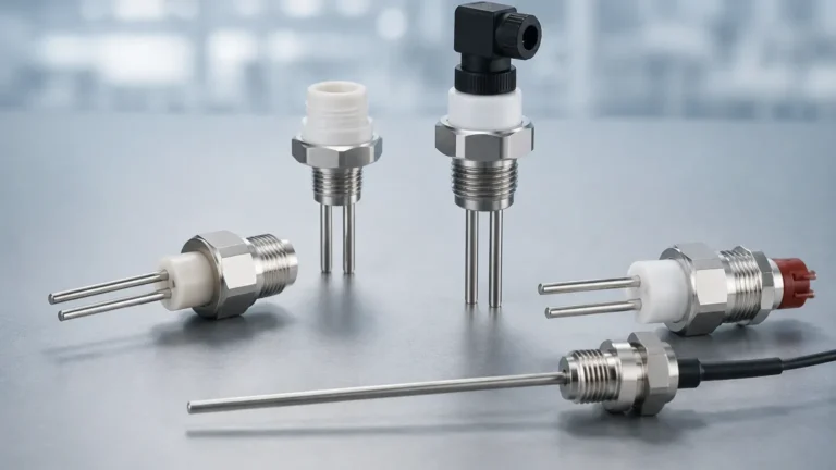
Cg381
Cg381
In the landscape of industrial automation and process control, the cg381 represents a critical advancement in precision level measurement technology. As industries move toward higher levels of efficiency and safety, the demand for non-contact or high-reliability contact-based sensing has surged. The cg381 series, specifically engineered for challenging environments, addresses the complexities of measuring liquids, solids, and slurries across various vessel types. This article provides a comprehensive technical overview of the cg381, its underlying measurement principles, selection criteria, and installation best practices to ensure optimal performance in B2B industrial applications.
Measurement Principles of the cg381 Series
Understanding the physics behind the cg381 is essential for proper application engineering. Most instruments within this designation utilize high-frequency radar technology, typically operating in the 80 GHz band, or advanced guided wave radar (GWR) principles.
Frequency Modulated Continuous Wave (FMCW)
For non-contact cg381 variants, the FMCW principle is standard. The instrument emits a continuous radar signal with a frequency that changes linearly over time (a frequency sweep). The signal travels to the surface of the medium, reflects, and returns to the sensor. By the time the reflected signal is received, the emission frequency has changed. The difference between the emitted and received frequencies ($Δf$) is directly proportional to the time of flight, and thus the distance to the product surface.
This high-frequency approach (80 GHz) allows for a narrower beam angle, which is a hallmark of the cg381 series. A narrower beam minimizes interference from internal tank structures such as agitators, heating coils, or ladders, providing a much cleaner signal-to-noise ratio compared to older 6 GHz or 26 GHz systems.
Guided Wave Radar (GWR)
In applications where the cg381 is configured as a contact-based probe, it utilizes Time Domain Reflectometry (TDR). Low-energy electromagnetic pulses are sent along a physical probe (cable or rod). When these pulses reach the surface of the medium, the change in the dielectric constant causes a reflection. The instrument measures the time taken for the pulse to return, calculating the level with millimeter precision. This method is particularly effective for media with low dielectric constants or in vessels with heavy steam or foam that might scatter a non-contact signal.
Key Technical Specifications and Performance
The cg381 is designed to bridge the gap between standard commercial sensors and heavy-duty process instruments. Below are the typical performance parameters encountered in industrial deployments:
* Measurement Range: Up to 30 meters (standard) or 120 meters (extended range for large silos).
* Accuracy: ±2 mm under reference conditions.
* Frequency: 76 GHz to 81 GHz for non-contact models.
* Process Temperature: -40°C to +250°C (with specialized cooling fins or high-temp gaskets).
* Process Pressure: Vacuum to 40 Bar (4.0 MPa).
* Output Signal: 4-20mA with HART protocol, Modbus RS485, or Foundation Fieldbus.
These specifications allow the cg381 to be integrated into modern Distributed Control Systems (DCS) and Programmable Logic Controllers (PLC), facilitating real-time monitoring and automated inventory management. To explore the full range of compatible hardware and integration modules, professionals often consult the Main Page of the manufacturer's technical portal.
Selection Criteria: Choosing the Right cg381 Configuration
Selecting the appropriate cg381 model requires a detailed analysis of the process medium and the vessel geometry. The following table serves as a practical selection guide for engineering teams.
| Feature | cg381-Standard (Non-Contact) | cg381-H (High Temp/Pressure) | cg381-G (Guided Wave) |
| :— | :— | :— | :— |
| Primary Application | Water treatment, chemical storage | Oil & Gas, steam boilers | Low DK liquids, solids |
| Max Range | 30 m | 25 m | 75 m |
| Beam Angle | 3° to 8° | 6° | N/A (Guided) |
| Material Compatibility | PP, PTFE, Stainless Steel | 316L Stainless, Hastelloy | 316L, PFA Coated |
| Dielectric Constant (εr) | > 2.0 | > 1.6 | > 1.4 |
| Mounting | G1½" or Flange | High-pressure Flange | Threaded or Flange |
Critical Evaluation Factors
1. Dielectric Constant (εr): The reflectivity of the signal depends on the dielectric constant of the material. For materials with very low εr (like certain oils or liquefied gases), a guided wave version of the cg381 is often preferred to ensure signal stability.
2. Vessel Internal Geometry: If the tank contains complex internals, the 80 GHz non-contact cg381 is superior due to its narrow beam, which can "steer" past obstructions.
3. Process Conditions: High turbulence or heavy foam can dissipate radar signals. In these instances, choosing a cg381 with advanced signal processing algorithms (False Echo Suppression) is mandatory.
Installation Best Practices for cg381 Instruments
Correct installation is the most significant factor in the longevity and accuracy of a cg381 deployment. Even the most advanced sensor will fail if the physical mounting environment is poorly prepared.
Nozzle Considerations
The nozzle height and diameter are critical. For non-contact cg381 units, the sensor face should ideally protrude slightly below the nozzle or be recessed only within specific limits to prevent "ringing" or internal reflections within the nozzle neck.
* Standard Nozzle: Diameter should be at least 50 mm for 80 GHz units.
* Protrusion: Ensure the antenna extends at least 10 mm past the nozzle bottom if using a horn antenna.
Positioning and Orientation
* The 1/6th Rule: For cylindrical tanks with flat or dished bottoms, the cg381 should ideally be installed at 1/6th of the tank diameter from the side wall. This avoids the center (where multiple reflections can converge) and the wall (where parasitic reflections occur).
* Avoid the Fill Stream: Never install the sensor directly above the inlet pipe. The falling product will create significant noise and may damage the sensor over time.
* Beam Path: Ensure the path of the radar beam is clear of agitator blades. If an agitator is present, the cg381's software must be used to map and ignore the echoes generated by the blades during a full rotation.
Environmental Protection
While the cg381 is typically rated IP67 or IP68, extreme outdoor environments require a sunshade to prevent temperature-induced electronic drift and to protect the housing from UV degradation. In cold climates, ensuring the process connection is insulated can prevent condensation or icing on the antenna face, which could attenuate the signal.

Industrial Applications and Use Cases
The versatility of the cg381 makes it a staple in several key sectors:
1. Water and Wastewater Treatment
In wastewater applications, the cg381 is used for monitoring open channel flow, chemical tank levels (such as sodium hypochlorite), and sludge levels. Its non-contact nature is vital here, as it prevents corrosion and fouling from the harsh, often debris-laden water.
2. Chemical Processing
Chemical reactors often involve high temperatures and corrosive vapors. The cg381 variants with PTFE-coated antennas provide the necessary chemical resistance while maintaining high accuracy, even when the medium is agitated or under pressure.
3. Food and Beverage
With hygienic process connections (Tri-Clamp), the cg381 is used in milk silos, brewery fermentation tanks, and syrup storage. The ability to withstand CIP (Clean-in-Place) cycles without recalibration is a significant operational advantage.
Limitations and Operational Constraints
Despite its advanced capabilities, the cg381 is not a universal solution for every scenario. Engineers must be aware of its limitations:
* Heavy Foam: Extremely thick, dense foam (like that found in certain detergent manufacturing) can absorb radar signals entirely. In such cases, a hydrostatic level transmitter or a magnetic level gauge might be a better alternative.
* Extremely Low Dielectric Media: Materials with a dielectric constant below 1.4 may not reflect enough energy for a standard non-contact radar. A bypass chamber or a guided wave probe is usually required.
* Dust and Build-up: While 80 GHz radar can penetrate some dust, extreme build-up on the antenna face can eventually lead to signal loss. Regular inspection or the use of a compressed air purge connection is recommended for heavy dust environments (e.g., cement or flour silos).
Frequently Asked Questions (FAQ)
Q: How often does the cg381 require recalibration?
A: Under stable process conditions, the cg381 is a "set and forget" instrument. Because it has no moving parts and the timing circuitry is crystal-controlled, annual verification is usually sufficient for regulatory compliance, rather than a full recalibration.
Q: Can the cg381 measure interface levels between two liquids?
A: Yes, the guided wave version (cg381-G) is specifically capable of measuring both the total level and the interface level (e.g., oil over water), provided the upper liquid is non-conductive and has a lower dielectric constant than the lower liquid.
Q: What is the "Blind Zone"?
A: The blind zone (or dead band) is the area immediately below the sensor where measurements are not possible. For the cg381, this is typically between 50 mm and 200 mm depending on the antenna type. This must be factored into the tank's maximum fill height.
Q: Is the cg381 compatible with existing 4-20mA loops?
A: Absolutely. It is designed to be a drop-in replacement for older ultrasonic or pressure-based sensors, utilizing standard two-wire loop power.
Conclusion
The cg381 stands as a robust, high-precision solution for modern industrial level measurement. By leveraging high-frequency radar and sophisticated signal processing, it provides reliability where traditional methods fail. Successful implementation relies on a thorough understanding of the process medium, careful selection of the probe or antenna type, and adherence to rigorous installation standards. For further technical support, application-specific data sheets, and procurement options, please visit the Main Page to connect with an application engineer.