Liquiphant
Liquiphant
In the field of industrial automation and process safety, point level detection serves as a critical fail-safe mechanism. Among the various technologies available, the vibrating fork level switch—frequently referred to by the industry-standard term Liquiphant—has established itself as a highly reliable solution for liquid applications. This technology is designed to prevent tank overfills, protect pumps from dry running, and provide high-accuracy level signaling across a diverse range of industries, including chemical processing, water treatment, and oil and gas.
Understanding the operational mechanics, selection criteria, and installation requirements of these instruments is essential for engineers and plant managers tasked with maintaining process integrity. This article provides a technical overview of the Liquiphant technology, offering a practical reference for its implementation in modern industrial environments.
Measurement Principle of Vibrating Fork Level Switches
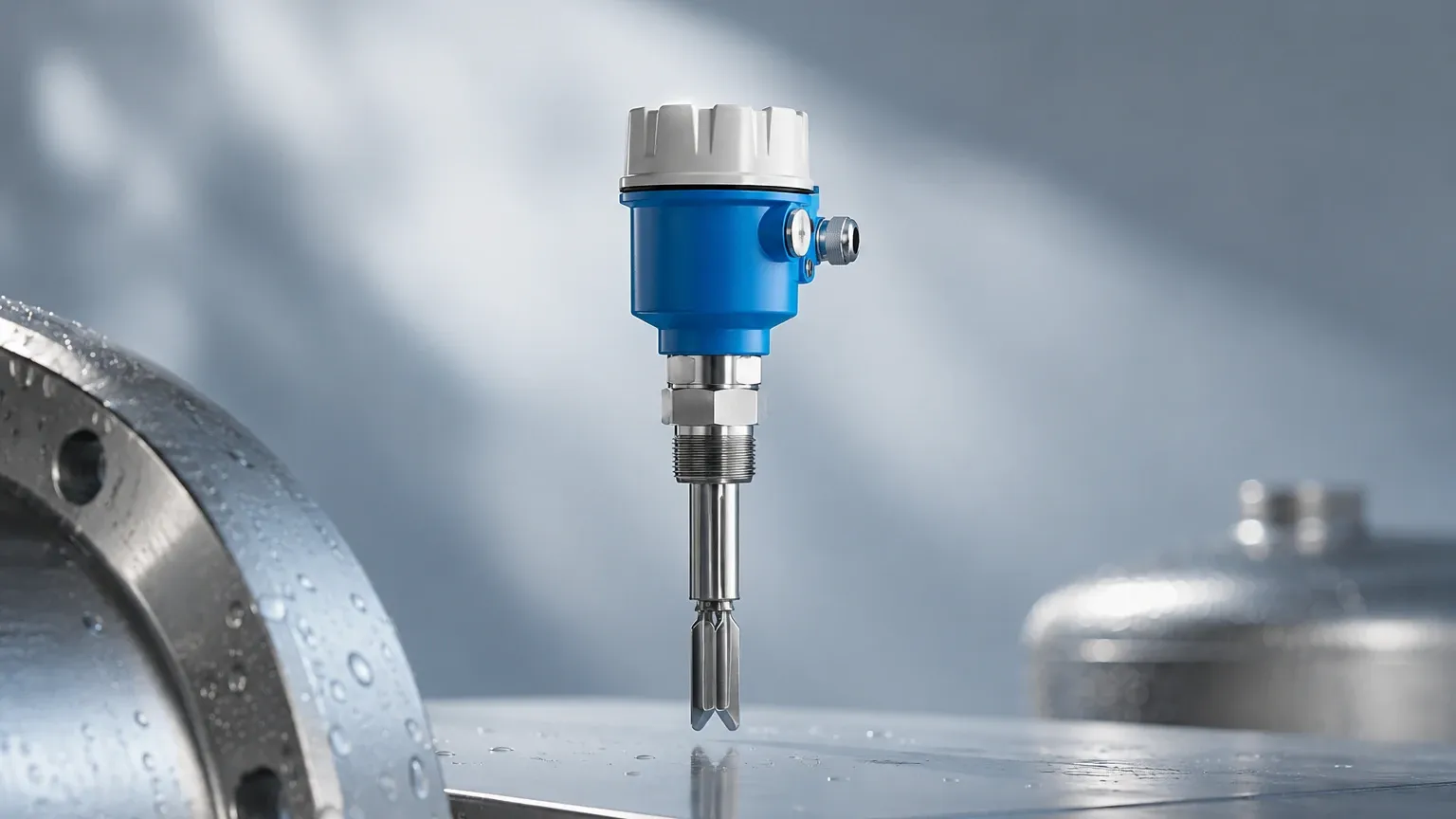
The Liquiphant operates on the principle of frequency shift in a vibrating element. The sensor head consists of a tuning fork that is excited to its resonant frequency by a piezoelectric drive. This drive typically consists of a stack of piezoelectric crystals that convert electrical energy into mechanical vibration and vice versa.
The Physics of Resonance
When the tuning fork is in the air (the "empty" state), it vibrates at its natural resonance frequency, which is determined by its mass and geometry. As soon as the fork is submerged in a liquid (the "covered" state), the density of the medium surrounding the tines increases the effective mass of the vibrating system. This increase in mass causes a significant drop in the vibration frequency.
Signal Processing
The internal electronics of the device continuously monitor this frequency. When the frequency drops below a predefined threshold, the electronics trigger a change in the output state (e.g., switching a relay or changing a current signal). Because the device relies on a physical change in vibration rather than electrical properties like conductivity or dielectric constant, it is largely unaffected by changes in the liquid's properties, such as foam, turbulence, or bubbles.
Key Applications for Liquiphant Technology
The versatility of the Liquiphant makes it suitable for a wide array of process tasks where reliability is paramount. Its primary roles include:
1. Overfill Prevention (High-Level Alarm)
This is the most common application. In storage tanks containing hazardous or expensive fluids, a Liquiphant is installed at the maximum allowable fill height. If the primary continuous level sensor fails, the vibrating fork provides an independent safety shut-off signal, often integrated into a Safety Instrumented System (SIS) with SIL2 or SIL3 ratings.
2. Pump Dry-Run Protection (Low-Level Alarm)
Centrifugal pumps can suffer catastrophic damage if they run without fluid (dry running). By installing a vibrating fork switch in the suction line or at the bottom of a supply tank, the system can automatically shut down the pump if the liquid level falls below the minimum required height.
3. Leak Detection
In double-walled tanks or containment bunds, Liquiphant sensors can be placed in the interstitial space to detect the presence of leaked liquid, providing early warning of primary vessel failure.
4. Phase Detection and Interface Monitoring
While primarily a point level switch, specialized versions can distinguish between different media based on density, allowing for the detection of oil-water interfaces or the presence of sediment in specific industrial processes.
Technical Selection Criteria
Selecting the correct Liquiphant model requires a detailed analysis of the process conditions. Unlike simple float switches, vibrating forks must be matched to the physical and chemical environment of the tank.
Density and Viscosity
The sensor must be calibrated for the minimum density of the liquid. Most standard units require a minimum density of 0.5 g/cm³ (500 kg/m³), though high-sensitivity models can detect fluids as light as 0.4 g/cm³. Viscosity also plays a role; while these sensors are robust, extremely high viscosity (above 10,000 mPa·s) can dampen the vibration to the point of false triggering.
Process Temperature and Pressure
Standard industrial models are typically rated for temperatures from -50°C to +150°C. For cryogenic or high-heat applications, specialized versions with temperature spacers or high-performance alloys can extend this range from -196°C to +280°C. Pressure ratings usually extend up to 64 bar (approx. 928 psi), though high-pressure variants can reach 100 bar.
Selection Table for Engineering Reference
| Parameter | Standard Industrial Specification | High-Performance Specification |
| :— | :— | :— |
| Minimum Medium Density | 0.7 g/cm³ | 0.4 g/cm³ |
| Viscosity Range | 1 to 10,000 mPa·s | Up to 10,000 mPa·s |
| Temperature Range | -40°C to +150°C | -196°C to +280°C |
| Max. Process Pressure | 40 bar (4.0 MPa) | 100 bar (10.0 MPa) |
| Wetted Materials | 316L Stainless Steel | Alloy C22, PFA Coating |
| Output Options | Relay, PNP, 2-wire AC/DC | 8/16mA, PFM, NAMUR |
Installation and Maintenance Considerations
Correct installation is critical to ensure the longevity and accuracy of the Liquiphant. Because the device relies on mechanical vibration, external factors can occasionally interfere with its performance.
Orientation and Positioning
* Horizontal Installation: When installed through the side of a tank, the tines should be oriented so that the liquid can easily drain off them. Most sensors have a marking (usually a notch or a dot) on the process connection that should point upwards or downwards to ensure the flat surfaces of the forks are vertical.
* Vertical Installation: When installed from the top of the tank, the length of the extension pipe must be calculated to reach the desired switching point. For turbulent liquids, a stilling well may be required to prevent mechanical stress on the long extension.
Avoiding Build-up and Obstructions
While the Liquiphant is designed to be somewhat self-cleaning due to its vibration, heavy build-up of solids or viscous "crusting" can eventually impede the fork's movement. It is important to install the sensor away from inlet streams where falling material might strike the tines or cause excessive wear.
Electrical Connection
Modern vibrating forks offer various electronic inserts. For integration into PLC systems, a 3-wire PNP output is common. In hazardous areas, NAMUR outputs or 2-wire AC/DC versions are often utilized to comply with Intrinsic Safety (IS) requirements.
Limitations and Common Risks
No measurement technology is universal. Engineers should be aware of the following limitations when specifying a Liquiphant:
1. Heavy Aeration: If a liquid is highly aerated (turning into a heavy foam or froth), the effective density may drop below the sensor's detection threshold, leading to a failure to switch.
2. Solid Particles: While small suspended solids are usually fine, large chunks or fibrous materials can become wedged between the tines, physically blocking the vibration and causing a permanent "covered" signal.
3. Turbulence: Extreme turbulence can exert lateral forces on the tines. In such cases, the use of a protective shield or a bypass pipe is recommended.
4. Coating: While the vibration sheds most liquids, products that harden or set (like drying glue or thick resins) can eventually coat the fork and stop the vibration entirely.
Comparison with Other Point Level Technologies
To understand why a Liquiphant might be chosen over other technologies, it is helpful to compare it to common alternatives found on the Main Page of industrial instrument catalogs.
* Float Switches: Float switches are mechanical and prone to sticking due to debris or corrosion. The Liquiphant has no moving parts (other than the microscopic vibration), making it significantly more reliable in dirty or corrosive liquids.
* Conductive Probes: Conductive switches require the liquid to be electrically conductive and can fail if the probe becomes coated. The Liquiphant is independent of conductivity and works equally well in oils, pure water, and chemicals.
* Ultrasonic Gap Switches: These use ultrasonic waves passed across a gap. While effective, they can be sensitive to bubbles and are generally more expensive than vibrating fork technology for standard applications.
* Capacitance Switches: Capacitance probes depend on the dielectric constant of the medium. If the moisture content or chemical composition of the liquid changes, the switch point may drift. The Liquiphant provides a much more stable switch point regardless of fluid composition changes.
Frequently Asked Questions (FAQs)
Q: Can the Liquiphant be used in solids or powders?
A: No. While the principle is similar, solids require a different fork geometry and vibration frequency (often called a "vibrating rod" or "soliphant") to account for the different damping characteristics of bulk solids.
Q: How do I test the device without filling the tank?
A: Most modern Liquiphant units include a test button or a magnetic test point. When activated, it simulates a frequency shift to verify that the electronics and the output relay are functioning correctly.
Q: Is the sensor affected by tank vibrations?
A: Generally, no. The resonance frequency of the fork is much higher (typically around 1000 Hz to 1400 Hz) than standard plant vibrations (usually below 100 Hz), so there is minimal risk of interference.
Q: What materials are available for corrosive liquids?
A: While 316L stainless steel is standard, tines can be coated with PFA, ECTFE, or manufactured from high-nickel alloys like Hastelloy (Alloy C22) for use in aggressive acids or bases.
Conclusion
The Liquiphant vibrating fork level switch represents a mature and highly dependable technology for point level detection. Its immunity to changing liquid properties such as conductivity, dielectric constant, and pressure makes it a "fit and forget" solution for many challenging industrial environments. By carefully considering the density, temperature, and chemical compatibility during the selection process, and following standard installation practices, engineers can ensure high levels of process safety and operational efficiency.
For more detailed technical specifications and to explore a full range of industrial measurement solutions, you may visit the Main Page to review product options and application support.