Radio Measurement
Radio Measurement
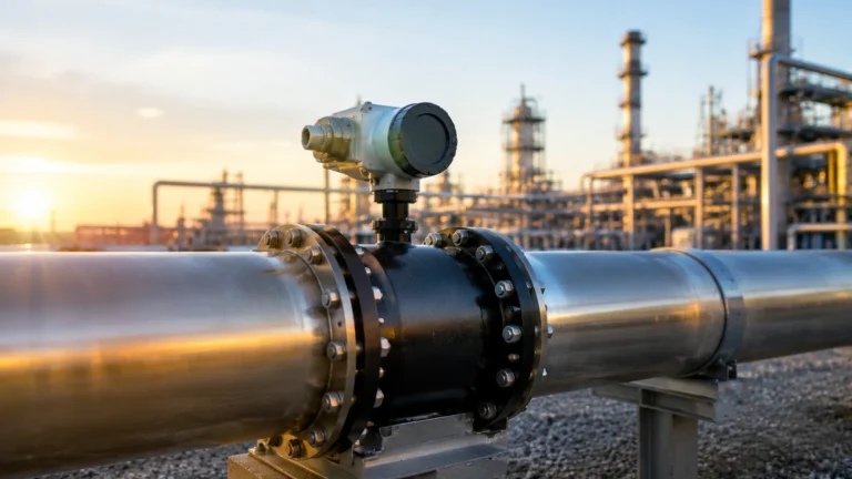
In the landscape of industrial automation and process control, radio measurement—specifically in the form of radar level technology—has emerged as the gold standard for accuracy and reliability. By utilizing electromagnetic waves in the microwave spectrum, these instruments provide non-contact or guided measurements of liquids, solids, and slurries across a vast range of temperatures and pressures.
For process engineers and plant managers, understanding the nuances of radio measurement is essential for optimizing inventory management and ensuring safety in hazardous environments. This guide explores the principles, applications, and selection criteria for implementing radio-based level measurement solutions.
Principles of Radio Measurement in Level Sensing
Radio measurement for level detection operates on the principle of reflecting electromagnetic waves off a target medium. Unlike ultrasonic sensors, which rely on sound waves and are influenced by air temperature and vapor composition, radio waves travel at the speed of light and are largely unaffected by the gas phase characteristics above the product.
Time of Flight (ToF)
At the core of most radio measurement devices is the Time of Flight principle. The instrument emits a high-frequency radio signal toward the material surface. When the signal hits the medium, a portion of the energy is reflected back to the sensor. The device measures the time interval between the emission and the reception of the echo. Since the speed of light is constant, the distance ($D$) is calculated as:
$$D = \frac{c \times t}{2}$$
Where $c$ is the speed of light and $t$ is the measured time. The level is then derived by subtracting this distance from the total tank height.
Pulse Radar vs. FMCW
There are two primary methods used in industrial radio measurement to determine the distance:
1. Pulse Radar: The transmitter emits a series of short microwave pulses. The receiver waits for the return signal before sending the next pulse. This method is energy-efficient and suitable for many standard applications.
2. Frequency Modulated Continuous Wave (FMCW): The transmitter sends a continuous signal with a constantly changing frequency. The difference between the frequency of the emitted signal and the reflected signal at any given moment is proportional to the distance. FMCW is generally more accurate and provides better signal-to-noise ratios, making it ideal for complex environments with turbulence or low-reflectivity products.
Types of Radio Measurement Systems
Industrial radio measurement is categorized into two main architectures: non-contact radar and guided wave radar (GWR).
Non-Contact Radar
Non-contact radar units are mounted at the top of a vessel and transmit signals through the air (or vacuum). Because they do not touch the process media, they are highly resistant to corrosive substances and are easy to maintain. They are further categorized by their operating frequency:
* 6 GHz (C-Band): Useful for applications with heavy foam or steam, as the longer wavelength can penetrate these obstacles better than higher frequencies.
* 26 GHz (K-Band): The standard for most industrial applications, offering a balance between beam focus and signal strength.
* 80 GHz (W-Band): Provides an extremely narrow beam angle, which is critical for avoiding internal tank obstructions like agitators or heating coils.
Guided Wave Radar (GWR)
Guided wave radar uses a physical probe (rod or cable) to direct the radio signal to the surface. This technology is based on Time Domain Reflectometry (TDR). The signal follows the probe, resulting in a highly concentrated energy path. GWR is particularly effective for:
* Low dielectric constant ($ε_r$) liquids.
* Interface measurement (e.g., oil over water).
* Vessels with narrow nozzles or complex internal geometries.
Key Evaluation Criteria for Radio Measurement
Selecting the right radio measurement instrument requires a deep dive into the physical properties of the media and the vessel environment.
Dielectric Constant (ε_r)
The dielectric constant of the material is the most critical factor in radio measurement. It determines how much energy is reflected back to the sensor.
* High ε_r (>10): Water-based liquids reflect signals strongly, making measurement easy.
* Low ε_r (1.4 to 4): Hydrocarbons and solvents reflect very little energy. In these cases, GWR or high-sensitivity non-contact radar (80 GHz) is often required.
Process Conditions
* Temperature and Pressure: Standard sensors may handle up to 150°C, but specialized high-temperature versions can withstand over 400°C. Pressure ratings can range from vacuum to 400 bar.
* Turbulence and Foam: Heavy foam can absorb radio signals. While 6 GHz radar can sometimes penetrate thin foam, thick, dense foam may require GWR or a different measurement technology entirely.
Vessel Geometry
The presence of ladders, pipes, and agitators can create "false echoes." Advanced radio measurement devices use software algorithms to "map" these obstructions and ignore them, focusing only on the true level signal. For those looking to explore specific equipment configurations for their facility, the Main Page of the manufacturer provides detailed technical data sheets and selection tools.
Practical Selection Table
| Feature | Non-Contact Radar (80 GHz) | Guided Wave Radar (GWR) | Pulse Radar (26 GHz) |
| :— | :— | :— | :— |
| Best Use Case | Small vessels, narrow beams | Interface, low dielectric | General liquid storage |
| Installation | Top-mounted, no contact | Probe must reach bottom | Top-mounted |
| Maintenance | Very Low | Moderate (probe cleaning) | Low |
| Foam Resistance| Moderate | High | Low to Moderate |
| Max Range | Up to 120m | Up to 75m | Up to 30m |
| Accuracy | ±1 mm | ±2 mm | ±3 mm to ±5 mm |

Installation Considerations
Proper installation is paramount to the success of radio measurement systems. Even the most advanced sensor will fail if placed incorrectly.
1. Nozzle Height and Diameter: For non-contact radar, the antenna should ideally extend slightly beyond the nozzle to prevent signal interference from the nozzle walls. If the nozzle is very long, a GWR or a lens antenna may be necessary.
2. Beam Angle and Obstructions: The "footprint" of the radio beam expands with distance. Ensure the beam path is clear of internal structures. 80 GHz sensors have a much narrower beam (typically 3° to 6°) compared to 26 GHz sensors (10° to 20°).
3. Dead Zones (Blocking Distance): Every radar has a minimum distance it can measure near the antenna. This is often called the "upper dead zone." Ensure the maximum fill level of the tank does not enter this zone.
4. Orientation: The sensor should be mounted vertically, perpendicular to the liquid surface. For solids, an aiming flange may be required to account for the angle of repose.
Limitations and Risks
While radio measurement is robust, it is not a universal solution. Engineers must be aware of the following limitations:
* Extremely Low Dielectrics: Materials with a dielectric constant below 1.4 (like certain liquefied gases) may not reflect enough energy for a standard non-contact radar to detect. In these instances, a stilling well or GWR is mandatory.
* Heavy Buildup: In GWR applications, if the media is highly viscous and coats the probe, it can cause signal attenuation or "ghost" levels. Non-contact radar is preferred for coating media.
* Vessel Material: Radio waves cannot pass through metal. However, they can pass through plastic or fiberglass tanks. This allows for "through-wall" measurement in specific non-metallic containers, though signal strength is reduced.
Frequently Asked Questions (FAQs)
1. Does dust affect radio measurement?
Unlike ultrasonic or optical sensors, radio waves are largely unaffected by dust. This makes radar the preferred choice for grain silos, cement bunkers, and fly ash hoppers.
2. Can radar measure the interface between two liquids?
Yes, Guided Wave Radar is specifically designed for this. A portion of the signal reflects off the upper liquid (low dielectric), while the remainder travels through it and reflects off the lower liquid (high dielectric, usually water).
3. How do I handle heavy turbulence from an agitator?
Using a sensor with a high update rate and advanced signal processing is key. Additionally, installing the sensor in a stilling well (a bypass pipe) can provide a calm surface for the radio measurement to reflect from.
4. Is radio measurement safe for food and beverage applications?
Yes. Many radar sensors are available with hygienic fittings (Tri-Clamp) and PTFE-encapsulated antennas that meet FDA and 3-A requirements, ensuring no contamination of the process media.
5. What is the difference between 26 GHz and 80 GHz?
The primary difference is the beam width and the size of the antenna. 80 GHz allows for much smaller antennas and a more focused beam, which is better for avoiding obstacles and measuring in small tanks.
Summary and Engineering Best Practices
Radio measurement has revolutionized level sensing by providing a high-precision, low-maintenance alternative to mechanical or pressure-based systems. When implementing this technology, remember the following best practices:
* Verify the Dielectric Constant: Always confirm the $ε_r$ of your media before selecting a sensor.
* Map the Tank: Use the instrument's software to perform a "false echo suppression" or "background mapping" during the commissioning phase while the tank is empty or at its lowest level.
* Consider Future Maintenance: While non-contact radar is low maintenance, ensure the mounting location is accessible for periodic verification or calibration.
For comprehensive support in selecting the appropriate frequency and probe configuration for your specific industrial application, visiting the Main Page will provide access to expert consultation and a wide range of industrial-grade level measurement instruments. By aligning technology choice with process realities, facilities can achieve unparalleled accuracy in their radio measurement strategies.