Cip Phase Change
Cip Phase Change
In the realm of industrial hygiene and process automation, the Clean-in-Place (CIP) system stands as a cornerstone for maintaining safety and quality standards, particularly in the food, beverage, and pharmaceutical sectors. A critical aspect of these systems is the management of the cip phase change. This term refers to the transition period between different fluids during a cleaning cycle—such as the transition from a product to a pre-rinse water, or from a caustic cleaning solution back to a final rinse.
Accurately detecting and managing these phase changes is essential for minimizing chemical waste, reducing water consumption, and ensuring that no residual cleaning agents contaminate the subsequent production batch. For process engineers, selecting the right level and interface measurement instrumentation is the primary method for achieving this precision.
Understanding the Principles of Phase Detection
Before selecting instrumentation to monitor a cip phase change, it is vital to understand the physical principles that allow sensors to distinguish between different liquids. In a typical CIP cycle, the fluids involved—water, acids, caustics, and the product itself—possess distinct physical properties.
Dielectric Constant and Radar Technology
Radar level meters, particularly Guided Wave Radar (GWR), rely on the dielectric constant (εr) of the medium. When an electromagnetic pulse travels down a probe and hits the surface of a liquid, a portion of that energy is reflected back. The strength of this reflection depends on the dielectric constant. Water has a high dielectric constant (approximately 80), while many oils or dry products have much lower values. During a phase change, a GWR sensor can detect the shift in the dielectric properties at the interface of two liquids or the change in the surface reflection as one fluid replaces another.
Electrical Conductivity
Conductivity is perhaps the most common method for detecting a cip phase change. Most cleaning chemicals, such as sodium hydroxide (caustic) or nitric acid, are highly conductive compared to deionized water or organic products. By measuring the electrical conductivity of the fluid in the pipe or tank, the system can trigger a valve to divert the flow once a specific threshold is reached, indicating that the cleaning solution has arrived or has been fully rinsed out.
Acoustic Impedance and Ultrasonic Sensors
Ultrasonic sensors measure the time it takes for a sound wave to travel to the liquid surface and back. While primarily used for level measurement, the speed of sound and the attenuation of the signal can change depending on the density and viscosity of the fluid. However, in CIP applications, ultrasonic sensors face challenges due to steam and temperature fluctuations, which can alter the speed of sound in the air gap above the liquid.
The Role of Level Measurement in CIP Cycles
A standard CIP cycle involves several distinct stages. Monitoring the cip phase change at each step ensures the system operates at peak efficiency.
1. Product Recovery (Pigging or Air Blow): Before cleaning starts, as much product as possible is recovered. Level sensors in the receiving tank must accurately track the volume to prevent overflow.
2. Pre-Rinse: Water is circulated to remove loose debris. The transition from product to water is the first critical phase change.
3. Caustic Wash: A heated detergent (usually 60°C to 90°C) is circulated. Detecting the arrival of the caustic solution allows the system to start the cleaning timer.
4. Intermediate Rinse: Water flushes out the caustic. Monitoring conductivity here prevents the mixing of caustic and acid.
5. Acid Wash: Used to remove mineral scale. Again, the cip phase change must be detected to manage chemical dosing.
6. Final Rinse: High-purity water ensures the system is chemically neutral and ready for production.
For a comprehensive view of how different instruments support these stages, you can Review product options and application support on our Main Page.
Selecting the Right Instrumentation for Phase Changes
Choosing the correct sensor depends on the specific fluid properties and the mechanical constraints of the processing environment. The following table provides a comparison of common technologies used to monitor phase transitions and levels during CIP.
Selection Table: CIP Level and Phase Detection
| Technology | Measurement Principle | Suitability for Phase Change | Advantages | Limitations |
| :— | :— | :— | :— | :— |
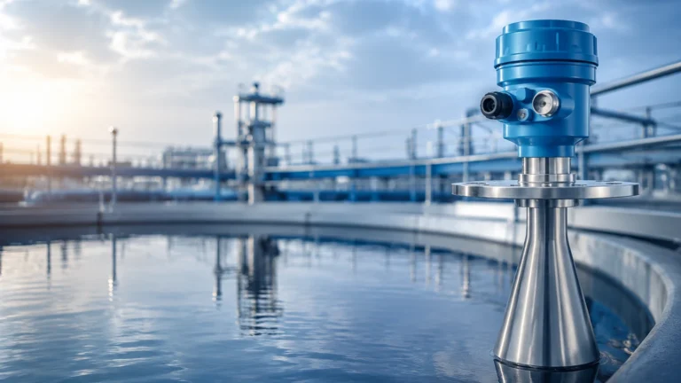
| Guided Wave Radar | Dielectric Constant | High | Ignores foam and steam; very accurate. | Contacting probe requires sanitary design. |
| Non-Contact Radar | Dielectric Constant | Medium | No contact with media; handles high pressure. | Can be affected by heavy foam. |
| Conductivity Probes | Electrical Resistance | Excellent | Fast response; low cost; industry standard. | Only works with conductive fluids. |
| Ultrasonic Sensors | Time of Flight (Sound) | Low | Non-contact; simple installation. | Sensitive to steam, foam, and temp changes. |
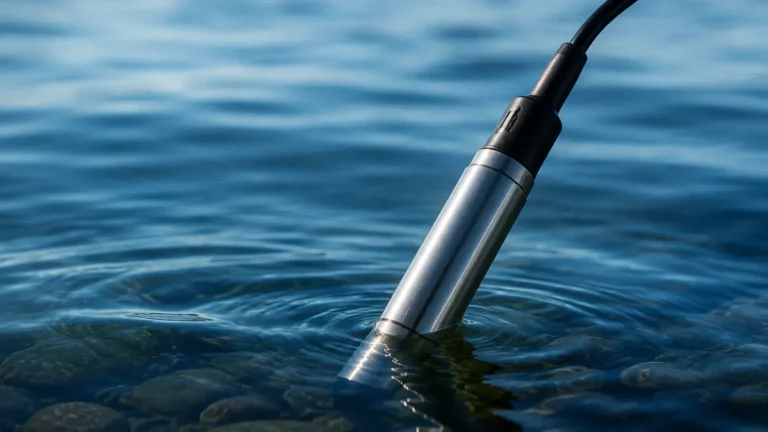
| Hydrostatic Pressure | Liquid Column Weight | Low | Reliable for volume; robust. | Density changes during CIP affect accuracy. |
Installation Considerations for Sanitary Environments
In industries where CIP is required, the installation of level meters must adhere to strict sanitary guidelines (such as 3-A or EHEDG). Improper installation can create "dead legs"—areas where fluid can stagnate and bacteria can grow, defeating the purpose of the cleaning cycle.
Mounting and Fittings
Sensors should be mounted using sanitary fittings, such as Tri-Clamps. The internal surface of the sensor that comes into contact with the process should have a surface roughness (Ra) of less than 0.8 μm to prevent microbial attachment.
Dead Leg Prevention
A dead leg is typically defined as a pocket of piping or a nozzle that is longer than two times its diameter (2D rule). When installing a sensor to detect a cip phase change, the nozzle length must be kept to a minimum to ensure that the cleaning fluid reaches the sensor face and the surrounding gasket area effectively.
Temperature Compensation
CIP processes involve rapid temperature swings, often jumping from 20°C to 90°C in a matter of minutes. Sensors must be equipped with internal temperature compensation to prevent measurement drift. For example, the diaphragm in a hydrostatic pressure transmitter may expand or contract, leading to false level readings if not properly compensated.

Challenges and Limitations in CIP Phase Monitoring
Despite the advanced technology available, several factors can complicate the detection of a cip phase change.
* Foam Interference: Many cleaning agents produce foam. Traditional ultrasonic and some non-contact radar sensors may struggle to distinguish between the liquid surface and the top of the foam layer. In these instances, Guided Wave Radar is often preferred because the signal follows the probe through the foam to the actual liquid level.
* Steam and Condensation: High-temperature cleaning and steaming (SIP) create heavy condensation on sensor faces. This can cause "blanking" in ultrasonic sensors. Radar sensors operating at higher frequencies (e.g., 80 GHz) are generally more resistant to the effects of condensation.
* Chemical Compatibility: The materials used in the sensor (such as PEEK, PTFE, or 316L Stainless Steel) must be resistant to the aggressive acids and bases used in the CIP process. Over time, incompatible materials may degrade, leading to sensor failure or process contamination.
Frequently Asked Questions (FAQs)
Q: Can I use a standard industrial level transmitter for CIP applications?
A: Generally, no. You must use a sanitary-grade version that features polished surfaces, food-grade gaskets, and a design that eliminates crevices where bacteria can grow.
Q: How does the dielectric constant change during a caustic-to-water transition?
A: While both are primarily water-based, the addition of salts in caustic solutions can slightly alter the dielectric properties, but more importantly, it significantly changes the conductivity. For phase change detection, conductivity is usually more sensitive than dielectric measurement.
Q: What is the impact of turbulent flow on phase detection?
A: Turbulence, often caused by high-velocity CIP pumps, can create signal noise. Using a stilling well or a guided wave radar probe can help stabilize the measurement during these periods.
Q: How often should CIP level sensors be calibrated?
A: Calibration frequency depends on the criticality of the process. However, because of the thermal shocks experienced during CIP, it is recommended to verify the zero-point of pressure-based sensors at least once every six months.
Conclusion: Optimizing the CIP Process
Effective management of the cip phase change is a hallmark of a sophisticated production facility. By integrating reliable level measurement and interface detection technologies, manufacturers can ensure that their cleaning cycles are both thorough and economical. Whether utilizing the precision of Guided Wave Radar or the rapid response of conductivity probes, the goal remains the same: a clean system with minimal downtime and resource waste.
For engineers looking to upgrade their current systems or design new installations, understanding the nuances of these technologies is the first step. To explore specific hardware solutions tailored to these industrial challenges, visit our Main Page at https://www.level-meters.com/ to view our full range of industrial level measurement instruments.