Conductive Probes
Conductive Probes
In the landscape of industrial level measurement, conductive probes represent one of the most reliable and cost-effective solutions for point-level detection in conductive liquids. Often referred to as conductivity switches or electrode level controllers, these devices are staples in water treatment, chemical processing, and food and beverage industries. Their lack of moving parts and straightforward electronic operation make them an engineered choice for applications where mechanical float switches might fail due to clogging or wear.
This guide explores the technical principles, selection criteria, and installation best practices for conductive probes, providing engineers and plant operators with the necessary framework to implement these sensors effectively.
Measurement Principle of Conductive Probes
The operation of conductive probes is based on the electrical conductivity of the process medium. For the system to function, the liquid must be capable of conducting an electrical current. This generally includes water-based liquids, acids, alkalis, and various aqueous solutions. Non-conductive liquids, such as oils, hydrocarbons, or pure distilled water, are not suitable for this technology.
The Electrical Circuit
At its core, a conductive level system consists of three main components: the probe (electrode), a reference ground, and a controller (relay).
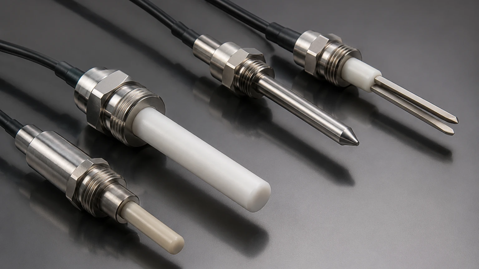
1. The Electrode: A stainless steel rod or a suspended cable that extends into the vessel to the desired switching point.
2. The Reference: If the tank is made of a conductive material (such as stainless steel), the tank wall itself acts as the reference electrode. In non-metallic or lined tanks, an additional "ground" probe must be installed, usually extending deeper than the lowest control probe.
3. The Controller: This unit applies a low-voltage alternating current (AC) to the electrodes.
When the conductive liquid rises and makes contact with the probe, an electrical circuit is completed between the probe and the reference ground. The controller detects the resulting current flow and switches an output relay. This relay can then trigger alarms, start or stop pumps, or open and close valves.
Why Use AC Instead of DC?
It is critical to note that professional-grade conductive probes utilize a low-voltage AC signal rather than Direct Current (DC). Using DC would lead to electrolysis, causing the buildup of ions on the probes (polarization) and eventually leading to the corrosion of the electrodes and inaccurate readings. AC signals prevent these electrochemical reactions, ensuring long-term stability and probe longevity.
Technical Selection Criteria
Choosing the right conductive probe requires an evaluation of both the fluid properties and the physical environment of the tank. Not all conductive probes are built for the same stresses.
Fluid Conductivity
The most important factor is the conductivity of the medium, measured in Microsiemens per centimeter (µS/cm). Most industrial controllers allow for sensitivity adjustments to match the specific liquid.
* High Conductivity (>1,000 µS/cm): Acids, lye, and wastewater. These are easy to detect and require low sensitivity settings.
* Low Conductivity (10 µS/cm to 100 µS/cm): Boiler feed water or some processed water. These require high-sensitivity controllers.
Probe Material and Construction
Depending on the chemical aggressiveness of the medium, the material of the electrode and the insulation must be selected carefully.
* 316L Stainless Steel: The standard for water and mild chemicals.
* Hastelloy or Titanium: Used for highly corrosive acids.
* Insulation (PTFE/PP): Probes are often partially insulated to ensure the electrical contact only occurs at the very tip, preventing false triggers from splashing or condensation on the upper part of the rod.
Selection Table: Rod vs. Cable Probes
| Feature | Rod Probes | Cable (Suspension) Probes |
| :— | :— | :— |
| Typical Length | 0.5m to 3m (1.6ft to 10ft) | 1m to 20m+ (3.3ft to 65ft+) |
| Installation | Top or Side-mounted | Top-mounted only |
| Best For | Agitated tanks, small vessels | Deep sumps, wells, large reservoirs |
| Maintenance | Easy to wipe clean | May require weights to stay vertical |
| Durability | High rigidity | Flexible; resistant to snapping |
Installation Considerations and Best Practices
Correct installation is paramount to preventing false switching and ensuring the safety of the control loop. Engineers should consult the Main Page of technical documentation for specific wiring diagrams, but the following general rules apply.
1. The Reference Electrode
In plastic, fiberglass (FRP), or concrete tanks, the liquid has no path to ground through the container. You must install a dedicated reference probe that is always submerged or at least reaches deeper than the lowest control probe. Without a solid reference point, the circuit cannot complete.
2. Avoiding Interference
Probes should be installed away from the tank's inlet to avoid false triggers caused by the incoming stream of liquid. If turbulence is high, the use of a stilling well (a pipe surrounding the probes) is recommended to provide a calm surface area for measurement.
3. Spacing and Insulation
In multi-point probes (where several rods are held in one flange), ensure that the rods do not touch each other. While most multi-point holders have spacers, buildup of conductive material (like sludge) between the rods can create a "bridge," causing the controller to think the tank is full when it is not. In such environments, fully insulated rods with only the tips exposed are mandatory.
4. Grounding and Shielding
To prevent electromagnetic interference (EMI) from nearby high-power equipment like large motors or VFDs (Variable Frequency Drives), use shielded cables for the connection between the probe head and the controller. The shield should be grounded at the controller end only.
Applications in Process Industries
Conductive probes are versatile and find use in various stages of industrial automation:
* Pump Control (Run-Dry Protection): A probe installed at the bottom of a tank ensures that a pump stops before it runs dry, preventing mechanical seal failure.
* High/Low Alarms: Providing redundant safety layers for overfill prevention in chemical storage.
* Boiler Water Level: Specialized high-temperature conductive probes are used to manage water levels in steam boilers, where the high pressure and temperature make other technologies less reliable.
* Wastewater Sumps: Because wastewater is highly conductive, these probes provide a low-maintenance way to manage lift station pumps.
Limitations and Risks
While highly effective, conductive probes are not a "universal" solution. Understanding their limitations prevents costly engineering errors.
* Coating and Buildup: If the liquid is prone to leaving a conductive film or crust (like some wastewater or syrups), the probe may stay "on" even after the level drops. This is known as "bridging."
* Non-Conductive Media: They cannot detect oils, diesel, or pure solvents. For these applications, ultrasonic or radar level meters are preferred.
* Foam: Conductive probes may detect heavy, wet foam as a liquid level. If the application involves significant foaming, a tuning fork or radar sensor might be more appropriate to distinguish between the foam and the actual liquid surface.
* Vessel Pressure: While the electrodes themselves are robust, the seals in the probe head must be rated for the specific process pressure and temperature.
Comparison with Other Point-Level Technologies
| Technology | Advantage | Disadvantage |
| :— | :— | :— |
| Conductive Probes | No moving parts, very low cost, simple electronics. | Requires conductive liquid, sensitive to coating. |
| Float Switches | Works with non-conductive liquids. | Moving parts can jam; prone to mechanical wear. |
| Vibrating Forks | Highly resistant to foam and buildup. | More expensive; complex electronics. |
| Ultrasonic (Point) | Non-contact. | Can be affected by steam, dust, or tank geometry. |
Frequently Asked Questions (FAQs)
Q: Can I cut the probe rods to length on-site?
A: Yes, most stainless steel rod-style conductive probes are designed to be cut to the specific depth required during installation. However, if the rods are PTFE-coated, you must carefully strip the insulation back at the tip (usually about 20-30mm) to ensure electrical contact.
Q: How do I test if a conductive probe is working?
A: You can perform a simple continuity test. With the controller powered, use a wire to jump the terminal of the probe to the ground/reference terminal. The relay should click. To test the probe itself in the tank, measure the resistance between the probe and the ground when submerged; it should drop from infinite to a low K-Ohm range depending on the liquid.
Q: What is the maximum distance between the probe and the controller?
A: This depends on the sensitivity of the controller and the conductivity of the liquid. Generally, distances up to 100 meters are possible, but shielded cable is required for long runs to prevent capacitive coupling and interference.
Q: Do conductive probes work in deionized (DI) water?
A: Generally, no. Deionized water has extremely low conductivity (often <1 µS/cm). Conductive probes typically require at least 5-10 µS/cm to operate reliably.
Conclusion
Conductive probes remain a primary choice for industrial level control due to their simplicity and durability. By understanding the electrical requirements of the fluid and the physical constraints of the vessel, engineers can design a level control system that requires minimal maintenance over years of operation. For high-demand environments, selecting the correct material and ensuring a proper reference ground are the most critical steps in the procurement process.
For further technical specifications, dimensional drawings, and integration support, engineers are encouraged to Review product options and application support to ensure the selected hardware meets the specific demands of their industrial automation project.