Conductivity Meter for Water
Conductivity Meter for Water
In industrial process control and water treatment, measuring the ability of an aqueous solution to carry an electrical current is a fundamental requirement. A conductivity meter for water serves as a critical diagnostic tool, providing an indirect measurement of the concentration of dissolved electrolytic substances, such as salts, acids, and bases. Whether in ultrapure water production for electronics or the management of cooling tower blowdown, selecting the correct conductivity instrumentation is essential for maintaining operational efficiency and equipment longevity.
Understanding Water Conductivity: Core Principles
Electrical conductivity (EC) in water is dictated by the presence of ions. These charged particles—cations (positive) and anions (negative)—act as conductors when a voltage is applied across electrodes submerged in the liquid. The standard unit of measurement is Siemens per meter (S/m), though in industrial water applications, it is more commonly expressed in microsiemens per centimeter (µS/cm) or millisiemens per centimeter (mS/cm).
The Relationship of Resistance and Conductance
Conductivity is the reciprocal of resistivity. While resistivity measures how strongly a material opposes the flow of current (measured in Ω·cm), conductivity measures how easily it flows. In ultrapure water applications, engineers often prefer resistivity units (e.g., 18.2 MΩ·cm), whereas for general process water, conductivity units are standard.
The Role of the Cell Constant (K)
The geometry of the conductivity sensor determines its "cell constant" (K). This is defined as the ratio of the distance (L) between the electrodes to the cross-sectional area (A) of the electrodes (K = L/A).
- Low Cell Constants (K=0.01 to 0.1): Used for low-conductivity liquids like deionized or ultrapure water, where electrodes are placed close together or have a large surface area.
- High Cell Constants (K=1.0 to 10.0): Used for high-conductivity liquids like seawater or chemical concentrates, where electrodes are spaced further apart to prevent current saturation.
Types of Conductivity Sensors for Industrial Water
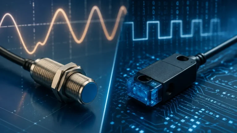
Choosing a conductivity meter for water requires an understanding of the two primary sensing technologies: contacting and inductive (toroidal).
1. Contacting Conductivity Sensors
Contacting sensors involve electrodes that come into direct physical contact with the process water. They typically utilize two or four electrodes.
- Two-Electrode Sensors: An AC voltage is applied between two electrodes, and the resulting current is measured. These are highly accurate for low-range measurements but are susceptible to "polarization errors" and fouling in high-conductivity or dirty environments.
- Four-Electrode Sensors: These use two drive electrodes and two sensing electrodes. This design minimizes the effects of polarization and cable resistance, making them suitable for a wider range of conductivity without changing the sensor.
2. Inductive (Toroidal) Conductivity Sensors
Inductive sensors operate without electrodes touching the process fluid. Instead, they use two wire-wound metal toroids encapsulated in a plastic or ceramic housing. One coil acts as a transmitter, inducing an electrical current in the conductive liquid, and the second coil acts as a receiver.
- Advantages: Since there are no electrodes to corrode or foul, inductive meters are ideal for wastewater, cooling water with high suspended solids, and concentrated chemicals. They are virtually maintenance-free in applications that would quickly degrade contacting sensors.
Key Evaluation Criteria for Engineering Specifications
When specifying a conductivity meter for water, engineers must look beyond the basic measurement range. Several environmental and process factors influence the reliability of the data.
Temperature Compensation
Conductivity is highly temperature-dependent; as the temperature of water increases, the mobility of ions increases, leading to higher conductivity readings (typically a 2% increase per degree Celsius). For accurate B2B process control, a meter must feature Automatic Temperature Compensation (ATC). This involves an internal temperature sensor (like a Pt100 or Pt1000 RTD) and software that references the reading back to a standard temperature, usually 25°C.
Material Compatibility
The sensor body and electrode materials must withstand the chemical properties of the water. Common materials include:
- 316L Stainless Steel: Standard for general water and high-pressure applications.
- Graphite: Excellent for general purpose and resistant to many chemicals.
- Titanium: Used for highly corrosive environments or seawater.
- PEEK/Polypropylene: Common for the encapsulation of inductive sensors in chemical processing.
Integration and Output
Modern industrial conductivity meters must integrate with PLC or SCADA systems. Standard outputs include 4-20mA analog signals, often with HART protocol, or digital communication via Modbus RS485 or Profibus. For facilities looking to centralize their fluid monitoring, including level and flow, consulting a comprehensive technical resource like the Main Page of an instrument specialist can provide insights into compatible system architectures.
Practical Selection Table for Industrial Applications
| Application Type | Typical Range | Recommended Sensor Type | Preferred Cell Constant (K) |
| :— | :— | :— | :— |
| Ultrapure Water (RO/DI) | 0.05 – 1.0 µS/cm | Contacting (Stainless Steel) | 0.01 |
| Boiler Feed Water | 1.0 – 50 µS/cm | Contacting (Stainless Steel) | 0.1 |
| Drinking/Potable Water | 50 – 1,000 µS/cm | Contacting (Graphite/SS) | 1.0 |
| Cooling Tower Water | 500 – 5,000 µS/cm | Inductive (Toroidal) | N/A |
| Wastewater/Effluent | 1,000 – 20,000 µS/cm | Inductive (Toroidal) | N/A |
| Chemical Concentration | Up to 2,000 mS/cm | Inductive (PEEK/Teflon) | 10.0 (if contacting) |
Installation and Calibration Best Practices
Correct installation is as vital as sensor selection. Improper placement can lead to air entrapment or stagnant flow, both of which result in erroneous readings.
1. Orientation: Sensors should be installed in a position where the sensing element is always fully submerged. In horizontal pipes, the sensor should be installed from the side or the bottom to avoid air bubbles that collect at the top.
2. Flow Direction: For contacting sensors, the flow should be directed against the face of the electrodes to ensure constant refreshing of the sample. For inductive sensors, ensure the "hole" of the toroid is aligned with the flow to prevent debris buildup.
3. Pipe Clearance: Inductive sensors require a minimum clearance from pipe walls (usually at least 2-5 cm) to prevent the pipe material from interfering with the magnetic field, unless the meter is calibrated specifically within that pipe.
4. Calibration: Conductivity meters should be calibrated using standard solutions that bracket the expected process range. For example, if the process water is typically 500 µS/cm, calibrate using a 1413 µS/cm standard. It is important to note that once a sensor is installed, "field calibration" should account for the specific cable length, as cable capacitance can affect the reading in high-precision applications.
Limitations and Potential Risks in Measurement
While robust, conductivity meters for water are not infallible. Users should be aware of the following risks:
* Fouling and Scaling: In contacting sensors, the buildup of calcium carbonate (scale) or biological slime on the electrodes acts as an insulator, leading to artificially low conductivity readings. Regular cleaning with mild acid or detergents is required.
* Polarization: In two-electrode sensors, at high conductivity, ions can build up near the electrode surface, creating a "back EMF" that resists current flow. This is why inductive or four-electrode sensors are preferred for high-salinity water.
* Non-Specific Measurement: Conductivity is a "bulk" measurement. It tells you that ions are present, but it cannot distinguish between different types of ions. For example, a conductivity meter cannot tell the difference between sodium chloride and magnesium sulfate in a water sample.
* Air Bubbles: Air is non-conductive. If air bubbles are trapped against the electrode or inside a toroidal sensor, the meter will report a much lower conductivity than actually exists in the process.
Frequently Asked Questions (FAQs)
Q: How often should a conductivity meter for water be calibrated?
A: In stable, clean water applications, quarterly calibration is often sufficient. In harsh industrial environments or wastewater, monthly or even weekly checks may be necessary to account for sensor coating or degradation.
Q: Can I use a conductivity meter to measure Total Dissolved Solids (TDS)?
A: Yes, most modern meters have a TDS mode. They calculate TDS by multiplying the conductivity reading by a conversion factor (typically between 0.5 and 0.7). However, since the exact composition of dissolved solids varies, this is always an approximation.
Q: What is the difference between conductivity and salinity?
A: Salinity is a measure of the total mass of dissolved salts in water (expressed in ppt or PSU). Conductivity is the measurement used to calculate salinity, specifically in seawater or brackish water applications.
Q: Does pipe material affect conductivity measurement?
A: For contacting sensors, no. For inductive (toroidal) sensors, metal pipes can interfere with the magnetic field if the sensor is too close to the wall. In such cases, a "wide-bore" installation or plastic pipe section is recommended.
Q: How does cable length affect the measurement?
A: For contacting sensors, long cables add resistance and capacitance, which can degrade the signal, especially at low conductivity. It is best to use a transmitter located close to the sensor or use a digital sensor that converts the signal at the probe head.
By adhering to these technical guidelines and selection criteria, process engineers can ensure that their water quality monitoring systems provide the reliable data necessary for complex industrial automation. For further technical specifications on integrated instrumentation for liquid management, professionals are encouraged to review the available resources and product options on the Main Page.