Insertion Vortex Flow Meter
Insertion Vortex Flow Meter
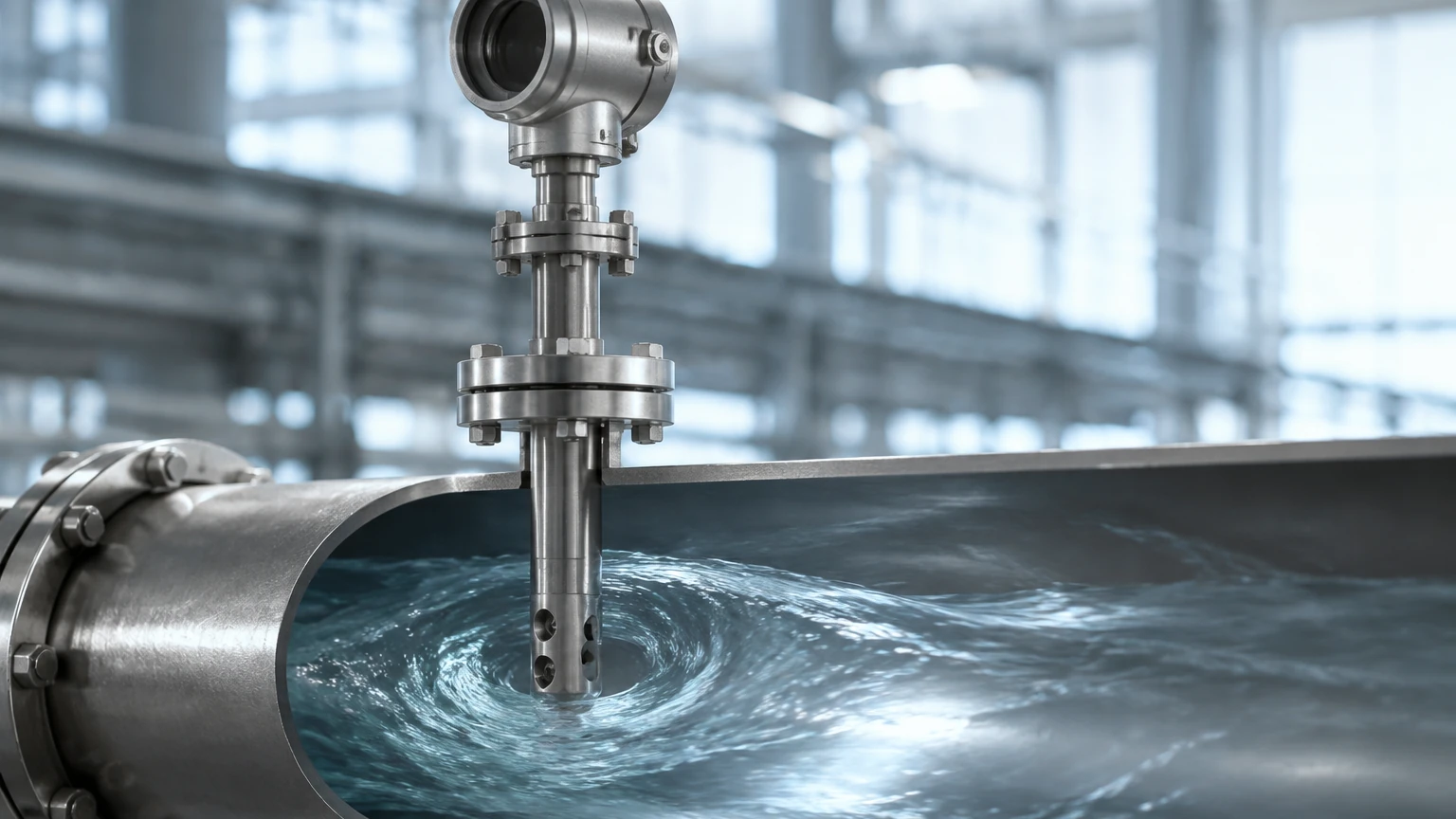
In the landscape of industrial fluid measurement, the insertion vortex flow meter serves as a critical instrument for monitoring the flow rates of gases, steam, and low-viscosity liquids within large-diameter piping systems. Unlike inline flow meters that require the replacement of a pipe section, insertion-style meters are designed to be introduced into the flow stream through a single mounting point, typically a flange or a thread. This design offers significant advantages in terms of installation cost, ease of maintenance, and the ability to perform "hot tapping"—installing the meter without shutting down the process line.
Measurement Principles of Vortex Shedding
The operation of an insertion vortex flow meter is based on the Von Kármán effect, a principle in fluid dynamics that describes the repeating pattern of swirling vortices caused by the unsteady separation of flow of a fluid around bluff bodies.
When a fluid—whether liquid or gas—encounters a non-streamlined object (known as a bluff body or shedder bar) within the sensor probe, it cannot follow the sharp contours of the object. This results in the fluid separating from the surface of the body and forming alternating areas of high and low pressure, which manifest as vortices. These vortices are shed from the sides of the bluff body in a staggered, alternating fashion.
The Strouhal Number
The frequency at which these vortices are shed is directly proportional to the velocity of the fluid. This relationship is defined by the Strouhal number ($St$), a dimensionless constant for a given bluff body shape over a wide range of Reynolds numbers. The formula is expressed as:
$$f = \frac{St \cdot v}{d}$$
Where:
* $f$ is the vortex shedding frequency.
* $St$ is the Strouhal number.
* $v$ is the fluid velocity.
* $d$ is the width of the bluff body.
Inside the probe of the insertion vortex flow meter, a piezoelectric crystal or a similar sensing element detects the pressure fluctuations caused by these vortices. The electronics within the transmitter then convert this frequency into a volumetric flow rate. Because the shedding frequency depends only on the velocity and the geometry of the shedder bar, the measurement is relatively independent of fluid density, pressure, and temperature, provided the Reynolds number remains within the linear range of the instrument.
Design and Components of Insertion Vortex Meters
An insertion vortex flow meter consists of several key components engineered to withstand industrial environments while maintaining high accuracy.
1. The Probe: This is the long, cylindrical component that extends into the pipe. It must be manufactured from materials compatible with the process fluid, such as 316 stainless steel or Hastelloy.
2. The Shedder Bar (Bluff Body): Located at the tip of the probe, the shedder bar is the geometric element that generates the vortices. Its shape is critical for maintaining a stable Strouhal number.
3. The Sensor Element: Usually a piezoelectric crystal located behind or within the shedder bar. It converts mechanical pressure pulses into electrical signals.
4. The Transmitter: The housing that contains the signal processing electronics. It performs filtering, amplification, and conversion of the raw signal into standard industrial outputs like 4-20mA, pulse, or digital protocols like HART and Modbus.
5. Mounting Assembly: This includes the flange or compression fitting that secures the meter to the pipe. For applications requiring maintenance without process interruption, a ball valve and retraction mechanism are included for hot-tap capability.
Selection Criteria for Industrial Applications
Choosing the correct insertion vortex flow meter requires a thorough understanding of the process conditions. While these meters are versatile, they are most effective when the pipe diameter is large enough to justify the cost savings over inline models, typically starting at DN200 (8 inches) and extending up to DN2000 or more.
Practical Selection Table
| Parameter | Requirement/Range | Notes |
| :— | :— | :— |
| Fluid Type | Clean liquids, gases, saturated/superheated steam | Not suitable for multi-phase or highly viscous fluids. |
| Pipe Diameter | DN200 to DN2000 (8" to 80") | Smaller pipes usually utilize inline vortex meters. |
| Velocity Range (Liquid) | 0.5 m/s to 7 m/s | Lower velocities may not generate detectable vortices. |
| Velocity Range (Gas/Steam) | 5 m/s to 70 m/s | High velocities can cause sensor vibration or damage. |
| Temperature Range | -40°C to +250°C (Standard); up to 400°C (High Temp) | Integral electronics may require remote mounting at high temps. |
| Pressure Rating | Up to 4.0 MPa (Standard) | Higher ratings available with specialized flange designs. |
| Accuracy | ±1.5% to ±2.0% of rate | Accuracy is highly dependent on flow profile and installation. |
For engineers looking to integrate these instruments into a broader automation or monitoring system, it is essential to consult a professional manufacturer to ensure the hardware matches the specific chemical and physical properties of the media. For more information on product options and technical support, visit the Main Page.
Installation and Maintenance Best Practices
The accuracy of an insertion vortex flow meter is heavily influenced by the flow profile within the pipe. Because the sensor only measures velocity at a specific point (usually the center of the pipe or at a calculated insertion depth), a fully developed, non-turbulent flow profile is necessary.
Straight Pipe Run Requirements
To ensure measurement stability, the following straight pipe runs are generally recommended:
* Upstream: Minimum 20D (20 times the pipe diameter) after a single elbow. If there are multiple elbows or valves upstream, this may increase to 40D or 50D.
* Downstream: Minimum 5D to prevent back-pressure fluctuations from affecting the vortex shedding.
Insertion Depth
The probe must be inserted to the correct depth to sample the representative velocity of the fluid. In most industrial applications, the sensor is positioned at the centerline of the pipe. If the pipe is very large, some manufacturers provide calculations for "point velocity" correction factors to account for the logarithmic flow profile of turbulent fluids.
Orientation
* For Liquid: The meter should ideally be installed in a vertical pipe with upward flow to ensure the pipe is always full. In horizontal pipes, the probe should be mounted from the side to avoid air bubbles at the top or sediment at the bottom.
* For Steam/Gas: In horizontal pipes, mounting from the top or side is acceptable. However, for saturated steam, side mounting is preferred to prevent condensate from collecting in the sensor head.
Technical Limitations and Operational Constraints
While the insertion vortex flow meter is a robust and cost-effective tool, it has specific limitations that must be acknowledged during the engineering phase.
1. Reynolds Number Cut-off: Vortex shedding only occurs reliably above a certain Reynolds number (typically Re > 20,000). If the flow is too slow or the fluid is too viscous, the vortices will not shed, and the meter will read zero.
2. Vibration Sensitivity: Because the sensor detects pressure pulses, high levels of mechanical vibration in the piping system can introduce "noise" that the transmitter might misinterpret as flow. Modern meters use digital signal processing (DSP) to filter this out, but extreme vibration should still be avoided.
3. Fluid Cleanliness: While the shedder bar is robust, large solids or fibrous materials can snag on the probe, disrupting the vortex pattern or damaging the sensor.
4. Pressure Drop: Although much lower than an orifice plate, the insertion probe does cause a small permanent pressure loss, which must be accounted for in low-pressure gas systems.
Frequently Asked Questions (FAQs)
Q: Can an insertion vortex flow meter measure mass flow?
A: Standard models measure volumetric flow. However, many modern transmitters include integrated temperature and pressure sensors (multivariable models) to calculate the compensated mass flow of steam and gases automatically.
Q: What is the benefit of "Hot Tapping"?
A: Hot tapping allows the installation of the flow meter while the pipe is under pressure. By using a weld-o-let, a ball valve, and a specialized retraction tool, the probe can be inserted into the stream without stopping production, saving significant downtime costs.
Q: How often does the meter need calibration?
A: Since there are no moving parts to wear out, the meter's factor (K-factor) remains stable over time. Recalibration is typically recommended every 2 to 3 years, or as required by local regulatory standards, primarily to verify the electronics and the integrity of the piezoelectric sensor.
Q: Is it suitable for hazardous areas?
A: Yes, most industrial insertion vortex flow meters are available with explosion-proof or intrinsically safe certifications (such as ATEX, IECEx, or UL) for use in chemical plants and refineries.
By adhering to these technical guidelines and understanding the underlying physics of vortex shedding, process engineers can successfully implement insertion vortex flow meters as a reliable, long-term solution for large-scale flow measurement. For specific application engineering or to review available models, please refer to the resources available on the Main Page.