Continuous Level Transmitters
Continuous Level Transmitters
In the landscape of industrial automation and process control, the ability to monitor the volume or height of materials in real-time is fundamental to operational efficiency and safety. Unlike point level switches, which only indicate whether a substance has reached a specific threshold, continuous level transmitters provide an uninterrupted output representing the exact level within a vessel. This data is critical for inventory management, preventing overfills, ensuring pump protection, and maintaining precise mixing ratios in chemical and water treatment processes.
Selecting the appropriate technology requires a deep understanding of the physical principles governing different sensor types. As a professional manufacturer, Welk provides a range of solutions including radar, ultrasonic, hydrostatic, and magnetic instruments designed to meet the rigorous demands of global industrial applications.
Understanding Continuous Level Measurement Principles
Continuous level measurement relies on converting a physical property—such as time-of-flight, pressure, or buoyancy—into an electrical signal, typically a 4-20mA loop, Modbus, or HART protocol. The choice of principle is dictated by the media (liquid or solid), the environment (vacuum, high pressure, or turbulence), and the required accuracy.
Time-of-Flight (ToF) Principles
ToF technologies, which include radar and ultrasonic sensors, measure the time it takes for a signal to travel from the sensor to the material surface and back. Because the speed of the signal (light or sound) is known, the distance can be calculated using the formula:
*Distance = (Speed × Time) / 2*.
Pressure-Based Principles
Hydrostatic measurement operates on the principle that the pressure at the bottom of a liquid column is directly proportional to the height of the liquid and its specific gravity. This is expressed as *P = ρgh*, where *P* is pressure, *ρ* (rho) is density, *g* is gravity, and *h* is the height of the liquid.
Displacement and Buoyancy
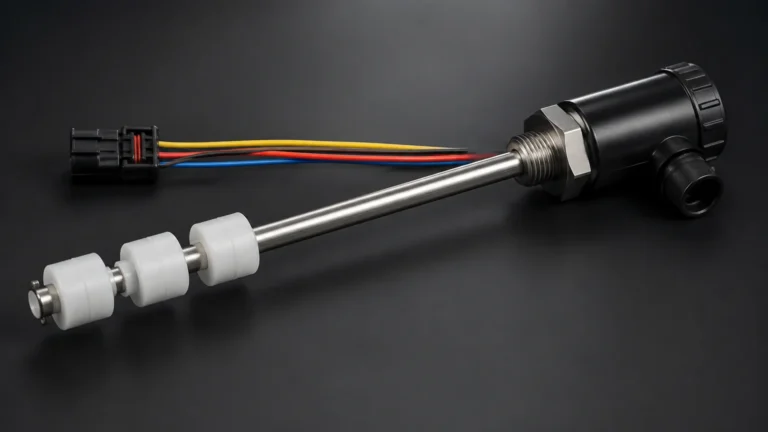
Mechanical continuous level transmitters often use magnetic floats. As the fluid level changes, a float moves along a guide tube. Inside the tube, a series of reed switches or a magnetostrictive wire detects the float's position, providing a continuous resistance or digital output.
Key Technologies for Continuous Level Transmitters
To ensure reliable data, engineers must match the transmitter technology to the specific process conditions. Below are the primary technologies utilized in modern industrial environments.
Radar Level Meters (Non-Contact and Guided)
Radar technology is widely considered the gold standard for challenging environments. It uses high-frequency electromagnetic waves (typically in the 6GHz, 26GHz, or 80GHz range).
* Non-Contact Radar: These emit signals through the air. They are unaffected by vacuum, high temperatures, or dust, making them ideal for chemical reactors and oil storage. High-frequency 80GHz radar allows for a narrow beam angle, which minimizes interference from internal tank structures like agitators or ladders.
* Guided Wave Radar (GWR): This technology uses a probe (cable or rod) to guide the radar pulse to the media surface. GWR is particularly effective for low dielectric constant liquids or applications with heavy foam, as the probe concentrates the signal energy.
For a comprehensive overview of high-precision radar options, you can Review product options and application support on our main site.
Ultrasonic Level Sensors
Ultrasonic transmitters emit high-frequency sound pulses. These are cost-effective solutions for water treatment and open-channel flow measurement. However, they are sensitive to air temperature variations (which change the speed of sound) and cannot be used in vacuums or high-pressure tanks where the medium for sound travel is absent or altered.
Hydrostatic Level Transmitters
These are often submersible or flange-mounted at the bottom of a tank. They are highly reliable for water, fuel, and chemical storage in vented tanks. Their primary limitation is that they are density-dependent; if the density of the liquid changes due to temperature or composition shifts, the level reading will drift unless compensated.
Magnetic Level Gauges with Transmitters
Magnetic level gauges provide a visual indication via a bypass chamber and can be fitted with a reed chain or magnetostrictive transmitter for continuous electronic feedback. These are preferred in high-pressure, high-temperature boiler applications where direct contact with the process fluid must be managed through a robust secondary containment (the bypass chamber).
Selection Criteria and Technology Comparison
Choosing between different continuous level transmitters involves balancing performance requirements against budget and installation constraints. The following table provides a general comparison of the most common technologies.
| Technology | Media Type | Max Range (Typical) | Accuracy | Key Advantage | Major Limitation |
| :— | :— | :— | :— | :— | :— |
| 80GHz Radar | Liquid/Solid | 30m – 120m | ±1mm | Highly accurate, narrow beam | Higher initial cost |
| Ultrasonic | Liquid/Slurry | 2m – 20m | ±0.25% | Non-contact, low cost | Affected by foam/vapor |
| Hydrostatic | Liquid | 1m – 200m | ±0.1% to 0.5% | Simple installation | Density dependent |
| Guided Wave Radar | Liquid/Solid | 6m – 30m | ±2mm | Works in foam/low dielectric | Contacting (probe buildup) |
| Magnetic Float | Liquid | 0.5m – 6m | ±5mm | Visual + Electronic | Moving parts can jam |
Installation Best Practices and Considerations
Proper installation is as critical as technology selection. Even the most advanced transmitter will fail to provide accurate data if positioned incorrectly.
1. The Dead Zone (Blocking Distance): Every ToF transmitter (radar and ultrasonic) has a "dead zone" directly beneath the sensor where it cannot measure. For ultrasonic sensors, this is typically 0.2m to 0.5m (8" to 20"). Ensure the maximum fill level of the tank does not enter this zone.
2. Nozzle Design: For radar and ultrasonic units, the mounting nozzle should be as short and wide as possible. If the nozzle is too long or narrow, the signal may reflect off the nozzle walls, creating "false echoes."
3. Obstruction Avoidance: Avoid mounting transmitters directly above inflow pipes, agitator blades, or heating coils. If obstructions are unavoidable, many modern radar transmitters offer "false wave suppression" software to mask these static reflections.
4. Positioning: Transmitters should generally be mounted at 1/2 to 1/3 of the tank radius from the wall. Mounting too close to the wall can cause signal interference, while mounting in the exact center can lead to multiple reflections in domed-roof tanks.
5. Venting: For hydrostatic transmitters in sealed tanks, a differential pressure setup or a vented cable is required to compensate for changes in atmospheric or headspace pressure.

Limitations and Common Application Risks
While continuous level transmitters are robust, certain process conditions present significant risks to measurement integrity:
* Heavy Foam: Foam can absorb ultrasonic and non-contact radar signals, leading to a "loss of echo." In these cases, Guided Wave Radar (GWR) or hydrostatic sensors are usually recommended.
* Vapor and Condensation: High concentrations of steam or chemical vapors can attenuate ultrasonic signals. For radar, condensation on the antenna can cause signal drift. Welk radar units often utilize PTFE-sealed antennas to mitigate the effects of corrosive condensation.
* Dust and Solids: When measuring bulk solids (like grain or cement), the material surface is rarely flat. It forms cones and pits. High-frequency radar with a narrow beam is required to accurately track the "average" level rather than reflecting off a single slope.
* Dielectric Constant (εr): Radar relies on the dielectric difference between the air and the media. If a liquid has a very low dielectric constant (e.g., certain hydrocarbons), the signal may pass through the liquid and reflect off the tank bottom instead. GWR is the preferred solution for low εr fluids.
Frequently Asked Questions (FAQ)
Q: Can I use one transmitter for multiple types of liquids?
A: If using radar or ultrasonic (ToF), yes, provided the dielectric constant or sound-reflecting properties are similar. If using hydrostatic, you must recalibrate the device if the liquid density changes significantly.
Q: How often do continuous level transmitters need calibration?
A: Non-contact radar and ultrasonic units are generally maintenance-free and do not drift over time. Hydrostatic and magnetic units should be checked annually for sensor fouling or mechanical wear.
Q: What is the difference between 26GHz and 80GHz radar?
A: 80GHz radar has a much smaller wavelength, allowing for a smaller antenna and a narrower beam (as small as 3 degrees). This makes it superior for small tanks or tanks with many internal obstructions compared to the wider beam of a 26GHz unit.
Q: Are these sensors suitable for hazardous areas?
A: Yes, most industrial transmitters are available with Ex-proof (Explosion-proof) or Intrinsic Safety (IS) ratings for use in oil, gas, and chemical environments.
Project Confirmation: Next Steps for Implementation
Before finalizing a purchase or specification for continuous level transmitters, project engineers should confirm the following technical parameters:
* Media Characteristics: Is the fluid corrosive, viscous, or prone to crystallization? What is the dielectric constant (for radar) or density (for hydrostatic)?
* Vessel Geometry: Provide the height, diameter, and the presence of any internal obstructions or agitators.
* Process Conditions: Define the maximum and minimum operating pressure (Bar/PSI) and temperature (°C/°F).
* Output Requirements: Determine if the control system requires 4-20mA, HART, RS485, or wireless transmission.
By addressing these factors early in the design phase, facilities can ensure long-term reliability and minimize the total cost of ownership for their level measurement infrastructure. For detailed technical specifications and customized OEM solutions, visit the Welk Main Page to explore our full range of industrial instrumentation.