Continuous Sampler
Continuous Sampler
In the realm of industrial process control and environmental monitoring, the ability to obtain representative data from a flowing stream or a stationary tank is paramount. A continuous sampler is a specialized instrument designed to collect samples from a process over a defined period, ensuring that the resulting composite sample accurately reflects the average characteristics of the medium. Whether in wastewater treatment, chemical processing, or oil and gas production, these systems work in tandem with precise instrumentation to maintain regulatory compliance and optimize operational efficiency.
For engineers and plant managers, understanding the synergy between a continuous sampler and level measurement technology is critical. While the sampler captures the physical medium, level sensors provide the necessary data to trigger sampling events, calculate flow-proportional volumes, and prevent reservoir overflows. This article explores the technical principles, selection criteria, and installation requirements for integrating continuous sampling systems with modern level measurement solutions.
Understanding Continuous Sampling in Industrial Processes
The primary objective of a continuous sampler is to eliminate the variability associated with "grab sampling." A grab sample only provides a snapshot of a process at a single point in time, which can be misleading if the process concentrations fluctuate. A continuous sampler, however, gathers small increments of the medium over time to create a composite sample.
Measurement Principles
There are three primary methods by which continuous sampling is executed, often dictated by the requirements of the specific application:
1. Time-Proportional Sampling: The sampler collects a fixed volume of the medium at regular, pre-defined time intervals (e.g., every 15 minutes). This is suitable for processes where the flow rate is relatively constant.
2. Flow-Proportional Sampling: This method is more complex and requires integration with a flow meter or a level-to-flow conversion system. The sampler collects a volume proportional to the flow rate. For instance, for every 1,000 liters that pass through a flume, a 100ml sample is taken. This ensures that the composite sample is representative of the total mass balance.
3. Event-Based Sampling: Sampling is triggered by a specific process condition, such as a pH spike or a sudden change in level. In these scenarios, the sampler acts as a diagnostic tool to capture data during process upsets.
The Role of Level Measurement in Sampling Systems
A continuous sampler rarely operates in isolation. To function accurately, it relies on high-precision level measurement instruments to provide real-time data. Level meters, such as those found on the Main Page of industrial instrument providers, are essential for the following functions:
Flow Calculation in Open Channels
In wastewater applications, continuous samplers are often placed near flumes or weirs. An ultrasonic level sensor or a radar level meter measures the head (height) of the liquid. Using standard hydraulic equations (like the Manning equation), the level data is converted into a flow rate. This flow rate then sends a pulse to the continuous sampler to initiate a collection cycle. Accuracy in level measurement is directly proportional to the accuracy of the flow-proportional sample.
Reservoir and Container Management
Once the sample is collected, it is stored in a composite container. To prevent the sampler from overfilling the container—which would lead to sample loss and potential environmental hazards—a level switch or a small-range hydrostatic level transmitter is used. When the container reaches 90% capacity, the level sensor sends a signal to the control system to halt the sampling process until the container is replaced.
Tank Profiling
In large-scale chemical or oil storage, a continuous sampler may be used to draw samples from different depths. Radar level meters provide the precise surface location, allowing the sampling probe to be positioned at specific increments (e.g., 1 meter below the surface) to ensure a representative vertical profile of the tank contents.
Technical Specifications and Selection Criteria
Selecting the right continuous sampler and its associated level instrumentation requires a thorough evaluation of the process environment. Engineers should consider the following technical factors:
Media Compatibility
The wetted parts of the sampler and the level sensor must be resistant to the chemicals being measured. For corrosive liquids, PTFE-coated radar sensors or non-contact ultrasonic meters are preferred. Similarly, the sampler’s tubing and pump head must be compatible with the acidity or alkalinity of the sample.
Solids Handling
If the medium contains suspended solids (common in mining or primary wastewater treatment), the continuous sampler must have a high suction velocity—typically at least 0.6 m/s (2 ft/s)—to prevent solids from settling in the intake line. Level sensors used in these environments must be able to ignore foam or surface turbulence caused by high solids loading.
Suction Head and Lift
The physical distance between the sampling point and the sampler is known as the suction head. Most peristaltic pump-based samplers can handle a vertical lift of up to 7 to 8 meters. If the level of the source liquid drops below this range, the sampler will fail to draw a volume. In these cases, a submersible hydrostatic level transmitter can be used to monitor the source level and ensure it remains within the sampler's operational limits.
Comparison Table: Sampling Methods and Level Integration
| Sampling Method | Level Sensor Requirement | Best Application | Key Advantage |
| :— | :— | :— | :— |
| Time-Weighted | Level Switch (High Limit) | Constant flow processes | Simple setup, low cost |
| Flow-Weighted | Ultrasonic or Radar (Head) | Wastewater/Effluent | Highly representative of total load |
| Depth-Integrated | Radar (Surface Tracking) | Large Storage Tanks | Captures vertical stratification |
| Event-Triggered | Hydrostatic (Rapid Change) | Stormwater monitoring | Captures data during upsets |
Installation Best Practices for Continuous Samplers
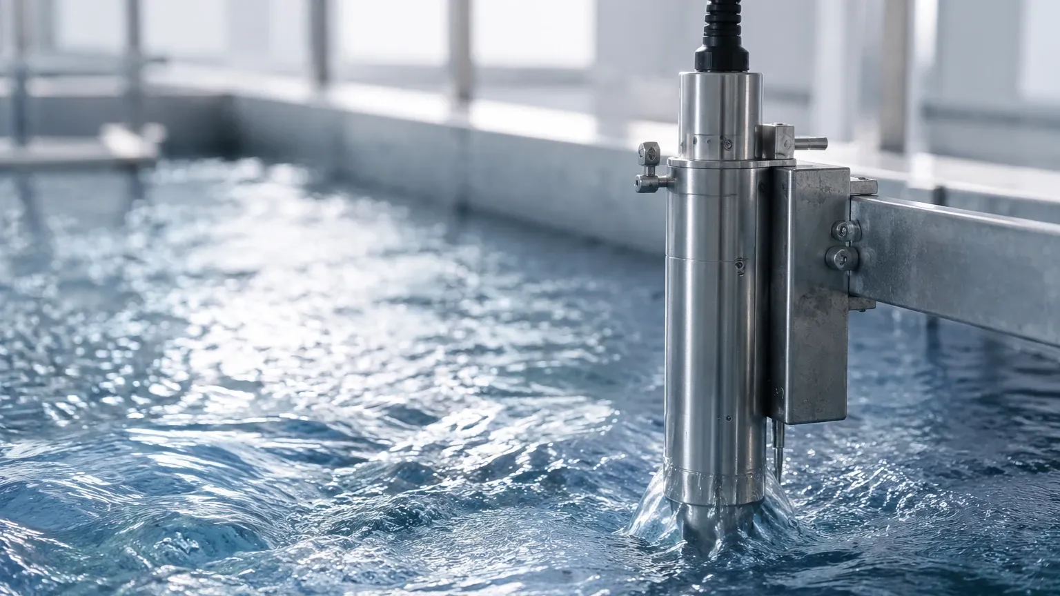
Proper installation is the difference between reliable data and frequent maintenance headaches. When integrating a continuous sampler with level measurement hardware, follow these engineering guidelines:
1. Sensor Placement: Ensure that the level sensor (ultrasonic or radar) is mounted in a location free from turbulence and away from the sampler's intake pipe. Turbulence created by the suction of the sampler can cause false level readings.
2. Stilling Wells: If the liquid surface is highly agitated, install the level sensor inside a stilling well. This provides a calm surface for accurate measurement, which in turn ensures the sampler is triggered at the correct intervals.
3. Intake Orientation: The intake for the continuous sampler should be oriented upstream and positioned in the center of the flow stream. Avoid placing the intake too close to the bottom where sediment accumulates, or too close to the surface where grease and floatables reside.
4. Calibration Alignment: The "zero point" of the level meter must be perfectly aligned with the floor of the channel or the bottom of the tank. Even a 5mm offset in level measurement can lead to significant errors in flow-proportional sampling volumes over a 24-hour period.
Common Challenges and Risk Mitigation
Despite their automation, continuous sampling systems face several operational risks that must be managed through proactive design.
* Clogging and Blockage: In high-solids applications, the intake line can become blocked. Modern samplers often feature a "pre-purge" and "post-purge" cycle where the pump reverses to blow air through the line before and after sampling. Integrating a pressure sensor can help detect these blockages early.
* Temperature Sensitivity: Biological samples must often be kept at 4°C (39°F) to prevent degradation. If the sampler is located outdoors in a hot climate, a refrigerated housing is necessary. Level sensors used in these cooled environments must be rated for low-temperature operation to avoid electronics failure due to condensation.
* Signal Interference: In industrial plants with heavy machinery, electrical noise can interfere with the 4-20mA signals sent from the level meter to the sampler. Using shielded cables and digital communication protocols like Modbus or HART can mitigate this risk.
Frequently Asked Questions (FAQs)
Q: How often should a continuous sampler be calibrated?
A: The sampler's volume accuracy should be checked monthly. However, the level meter providing the trigger signal should be verified every six months, as sensor drift is a common cause of sampling inaccuracies.
Q: Can I use a radar level meter for flow-proportional sampling?
A: Yes. Radar level meters are excellent for this purpose because they are non-contact and unaffected by steam, temperature, or pressure. They provide the high-accuracy head measurement needed for precise flow calculations.
Q: What happens if the power fails?
A: Most industrial continuous samplers have an internal battery backup that can maintain the sampling program for several hours. It is vital that the associated level meter is also connected to a backup power source so that the trigger signal is not lost.
Q: Is a continuous sampler required for EPA compliance?
A: In many jurisdictions, industrial discharge permits (NPDES in the US) require 24-hour composite samples for specific pollutants. A continuous sampler is the standard tool used to meet these legal requirements.
Conclusion
The integration of a continuous sampler with robust level measurement technology is a cornerstone of modern industrial monitoring. By understanding the principles of flow-proportional sampling and the technical requirements for sensor installation, facilities can ensure they collect representative samples that stand up to regulatory scrutiny. For those seeking to upgrade their process monitoring capabilities, exploring advanced level measurement options is the first step toward a more reliable sampling program. To review specific product options and application support for level instrumentation, visit the Main Page for detailed technical specifications.