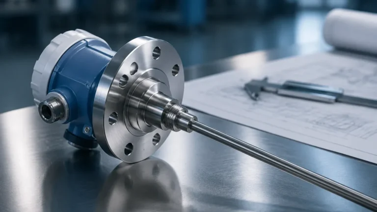
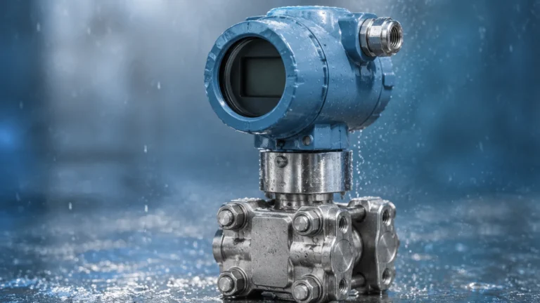
Flow Measurement System
Flow Measurement System
In industrial process control, a flow measurement system is a critical infrastructure component designed to quantify the movement of liquids, gases, or vapors through a specified conduit. Whether for custody transfer, chemical dosing, or wastewater management, the accuracy of flow data directly impacts operational efficiency, safety, and regulatory compliance. For engineers and facility managers, selecting the right system requires a deep understanding of fluid dynamics, sensor technology, and the specific constraints of the application environment.
While flow and level measurement are often treated as separate disciplines, they are frequently interdependent. In many industrial scenarios, particularly in open channel applications or tank inventory management, the data provided by high-precision level sensors is the primary variable used to calculate flow rates. As a professional manufacturer, Welk provides the foundational instrumentation—including radar and ultrasonic sensors—that powers these complex measurement systems.
Fundamental Principles of Flow Measurement
To implement an effective flow measurement system, one must first understand the physical principles governing the sensors. Flow measurement is generally categorized by the method used to derive the flow rate: mass, volume, or velocity.
1. Velocity-Based Measurement
Most industrial flowmeters measure the velocity of the fluid moving through a known cross-sectional area. The volumetric flow rate ($Q$) is then calculated using the formula $Q = A \times v$, where $A$ is the area and $v$ is the velocity. Technologies like ultrasonic and electromagnetic meters rely on this principle.
* Ultrasonic (Transit-Time): This method uses two transducers that send and receive ultrasonic signals. The time difference between the signal traveling with the flow and against the flow is proportional to the fluid's velocity.
* Electromagnetic: Based on Faraday’s Law of Induction, these meters measure the voltage generated when a conductive liquid moves through a magnetic field. The voltage is directly proportional to the flow velocity.
2. Differential Pressure (DP)
DP flow measurement systems utilize a primary element, such as an orifice plate or Venturi tube, to create a constriction in the pipe. This constriction causes a pressure drop. According to Bernoulli’s equation, the square root of this pressure difference is proportional to the flow rate. While traditional, these systems remain a staple in steam and high-pressure gas applications.
3. Open Channel Flow (Level-to-Flow)
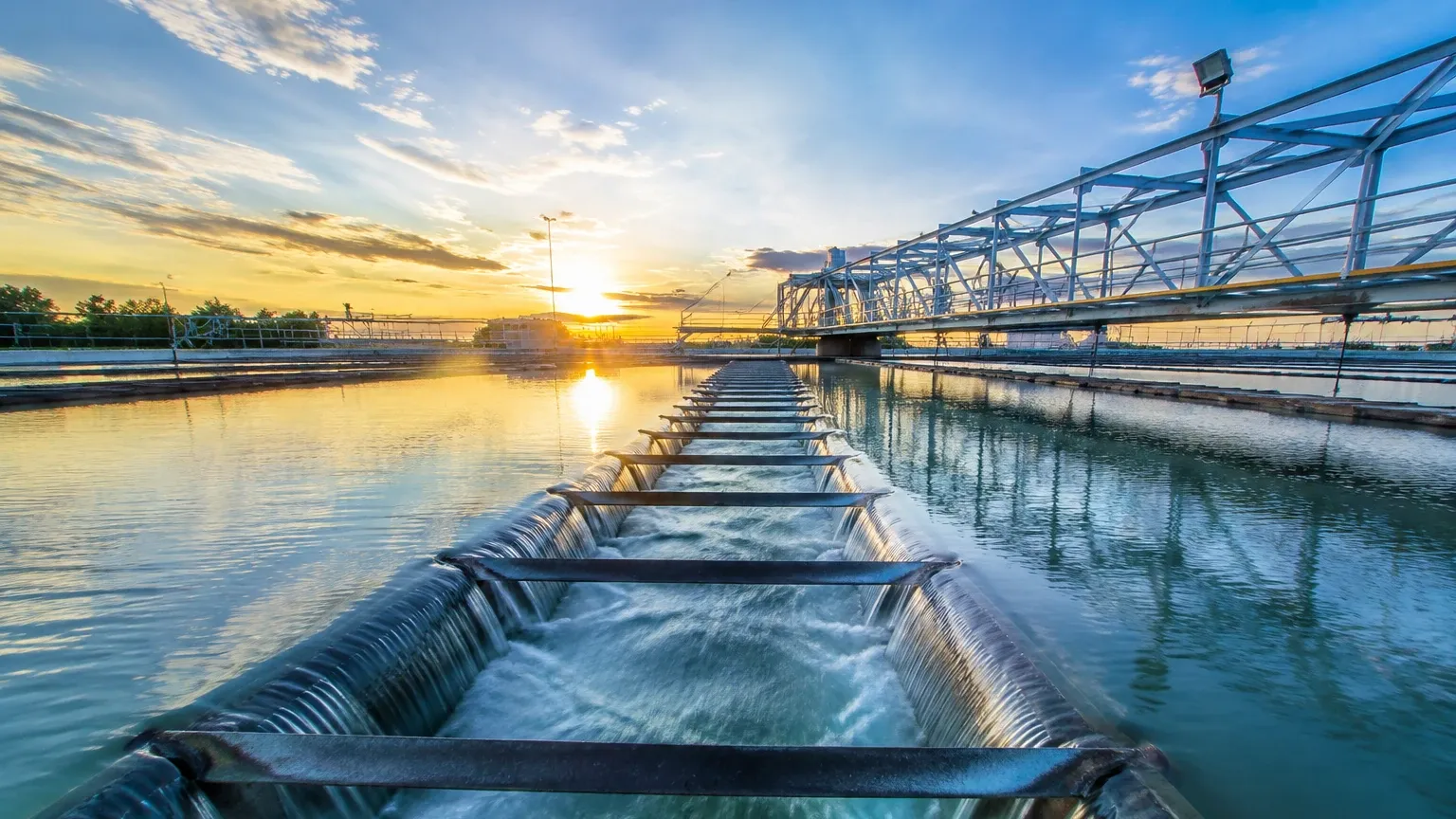
In many water treatment and irrigation projects, fluids move in open conduits rather than closed pipes. Here, the flow measurement system typically consists of a primary device (a weir or flume) and a secondary instrument (a level sensor). By measuring the head height (level) of the liquid as it passes through the weir or flume, the system applies standardized hydraulic formulas to determine the flow rate. This is where high-accuracy radar and ultrasonic level meters are indispensable.
Components of a Complete Flow Measurement System
A robust system is more than just a sensor; it is an integrated loop of components working in tandem:
1. Primary Element: The physical device that interacts with the fluid (e.g., the pipe section, the weir, or the orifice).
2. Transducer/Sensor: The component that detects the physical change (e.g., pressure, ultrasonic waves, or magnetic field).
3. Transmitter: Converts the sensor’s raw signal into a standardized electronic signal, such as 4-20mA, HART, or Modbus.
4. Flow Computer/Controller: The intelligence of the system that performs scaling, temperature/pressure compensation, and totalization.
Selection Criteria for Industrial Applications
Choosing the incorrect technology for a flow measurement system can lead to significant maintenance overhead or catastrophic process failure. Engineers should evaluate the following criteria before procurement:
Fluid Properties
* Conductivity: Electromagnetic meters require a minimum conductivity (usually >5 μS/cm). For non-conductive fluids like oils, ultrasonic or DP meters are preferred.
* Viscosity: High-viscosity liquids can create laminar flow profiles that affect the accuracy of certain velocity-based meters.
* Suspended Solids: Slurries and wastewater require non-clogging designs. Ultrasonic Doppler or electromagnetic meters are ideal here, whereas orifice plates would quickly erode or clog.
Process Conditions
* Pressure and Temperature: Ensure the sensor housing and seals can withstand the maximum process limits.
* Flow Range (Turndown Ratio): This is the ratio of the maximum flow to the minimum flow that the meter can measure accurately. If your process fluctuates significantly, a high turndown ratio is essential.
Selection Table: Technology Comparison
| Technology | Fluid Type | Typical Accuracy | Advantages | Limitations |
| :— | :— | :— | :— | :— |
| Electromagnetic | Conductive Liquids | ±0.5% | No moving parts; no pressure drop. | Requires conductive fluid. |
| Ultrasonic (Transit-Time) | Clean Liquids/Gases | ±1.0% | Non-invasive; clamp-on options. | Sensitive to bubbles/solids. |
| Radar (Open Channel) | Wastewater/Chemicals | ±2.0% | Non-contact; unaffected by steam. | Requires stable surface. |
| Differential Pressure | Gas, Liquid, Steam | ±1.0% to ±3.0% | Well-understood; handles extremes. | High pressure drop; high maintenance. |
| Vortex | Steam, Low-viscosity | ±1.0% | Excellent for steam applications. | Sensitive to vibration. |
Integration of Level Sensors in Flow Systems
In the context of the Main Page of industrial instrumentation, level sensors are often the unsung heroes of flow measurement. In open channel systems, the accuracy of the flow calculation is entirely dependent on the precision of the level measurement.
For example, in a Parshall flume, a 1% error in level measurement can result in a 1.5% to 2.5% error in calculated flow. Using a non-contact ultrasonic or radar level transmitter from Welk ensures that the sensor does not foul or corrode, maintaining long-term accuracy in harsh environments like sewage treatment plants. These sensors provide the "head" measurement that the flow computer uses to solve the specific discharge equation for that flume.
Installation Considerations and Best Practices
Even the most expensive flow measurement system will fail if installed incorrectly. Follow these engineering guidelines to ensure reliable data:
1. Straight Pipe Requirements
Most flowmeters require a fully developed flow profile to measure accurately. This usually means a minimum of 10 diameters (10D) of straight pipe upstream and 5 diameters (5D) downstream from the sensor. Elbows, valves, and pumps create turbulence that can skew velocity readings.
2. Pipe Orientation
For liquid applications, the pipe must always be full. Installing a meter in a vertical line with upward flow is often the best way to ensure the pipe remains full and to prevent air pockets. If installed horizontally, the sensor should not be at the very top (where air collects) or the very bottom (where sediment collects).
3. Grounding
Electromagnetic flow measurement systems are particularly sensitive to electrical noise. Proper grounding to the process liquid is essential to prevent stray currents from interfering with the small millivolt signals generated by the sensor.
4. Environmental Protection
In outdoor installations, sensors should be shielded from direct sunlight to prevent temperature-induced electronic drift. For ultrasonic systems, wind and heavy rain can occasionally interfere with the signal in open channel applications; using a protective stilling well or a radar-based sensor can mitigate these effects.
Common Risks and Limitations
* Aeration and Cavitation: Air bubbles in a liquid line can cause ultrasonic signals to scatter or cause electromagnetic meters to read erratically. Cavitation, caused by pressure drops across valves, can damage the internal components of a flowmeter.
* Scaling and Coating: In chemical or wastewater applications, material buildup on the internal walls of the meter or on the face of a level sensor can change the cross-sectional area or dampen the signal. Regular cleaning or selecting non-contact sensors is necessary.
* Reynolds Number Sensitivity: Many meters are calibrated for turbulent flow. If the flow becomes laminar (low Reynolds number), the accuracy may degrade significantly.
Maintenance and Calibration
To maintain the integrity of a flow measurement system, a regular calibration schedule is required. This can be done via:
* Master Meter Testing: Comparing the system against a highly accurate portable meter.
* Gravimetric Calibration: Weighing the amount of fluid passed through the system over a set time (the gold standard for accuracy).
* In-situ Verification: Modern digital transmitters often include self-diagnostic tools that verify the health of the internal electronics and sensor coils without removing the device from the line.
Frequently Asked Questions (FAQ)
Q: Can I use a level sensor to measure flow in a partially filled pipe?
A: Yes, this is known as the area-velocity method. You need to measure both the depth of the liquid (using an ultrasonic or radar sensor) and the velocity of the liquid (using a submerged probe). The system then calculates flow based on the wetted cross-sectional area.
Q: What is the advantage of radar over ultrasonic for open channel flow?
A: Radar is unaffected by air temperature fluctuations, wind, or steam, which can change the speed of sound and affect ultrasonic accuracy. Radar is generally preferred for high-precision or outdoor applications.
Q: How often should a flow measurement system be calibrated?
A: For most industrial applications, an annual calibration is standard. However, for custody transfer or high-value chemical dosing, semi-annual or quarterly checks may be required by regulatory bodies.
Q: Do I need a flow computer if my transmitter has a 4-20mA output?
A: While a PLC can often handle basic calculations, a dedicated flow computer is recommended for applications requiring complex compensation (like mass flow for gases) or where legal-for-trade totalization is required.
Conclusion
A flow measurement system is a vital tool for modern industrial automation. By selecting the appropriate measurement principle—whether it be electromagnetic, ultrasonic, or level-based—and adhering to strict installation standards, facilities can achieve the precision necessary for optimized production. For those building these systems, starting with reliable, high-performance sensors is the first step toward long-term operational success. For more information on the sensors that power these systems, Review product options and application support.