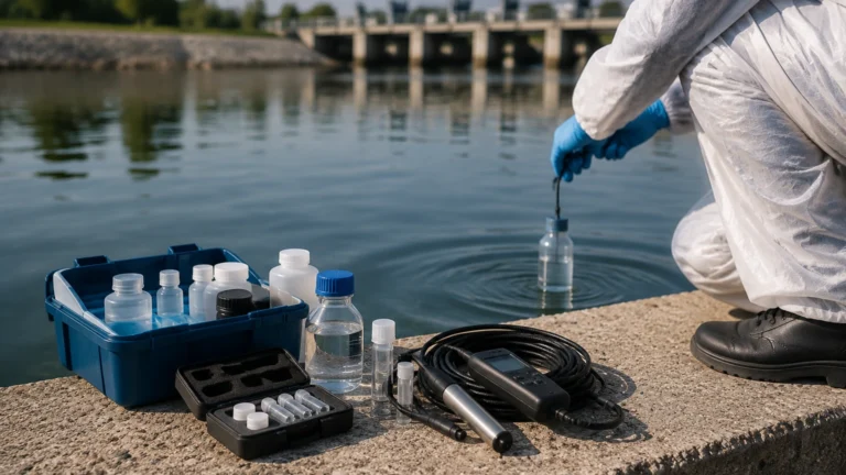
Resistivity Sensor
Resistivity Sensor
In the realm of industrial process control and liquid analysis, the resistivity sensor serves as a critical instrument for determining the purity of water and other low-conductivity fluids. While level measurement instruments like radar and ultrasonic sensors track the quantity of a medium, the resistivity sensor monitors its quality. For industries such as semiconductor manufacturing, pharmaceuticals, and high-pressure power generation, maintaining specific resistivity levels is not merely a preference but a fundamental requirement for operational integrity and product yield.
This guide explores the technical principles, selection criteria, and practical application of resistivity sensors within industrial environments, providing engineers with the necessary framework to integrate these devices into comprehensive liquid management systems. For those seeking a broader overview of integrated instrumentation for tank and process monitoring, visiting the Main Page of professional measurement providers offers insight into how these sensors complement level and pressure transmitters.
Measurement Principles of Resistivity Sensors
To effectively implement a resistivity sensor, one must first understand the physics governing its operation. Electrical resistivity is the reciprocal of electrical conductivity. While conductivity measures a fluid's ability to conduct an electric current (often used for high-salinity or chemical-heavy liquids), resistivity measures the fluid's opposition to that current.
The Relationship Between Resistance and Resistivity
The measurement is based on Ohm’s Law, which states that resistance (R) is equal to voltage (V) divided by current (I). In a liquid medium, the resistance depends on the geometry of the sensor electrodes and the distance between them. The formula for resistivity (ρ) is:
ρ = R × (A / L)
Where:
* R is the measured resistance (Ohms).
* A is the cross-sectional area of the electrodes.
* L is the distance between the electrodes.
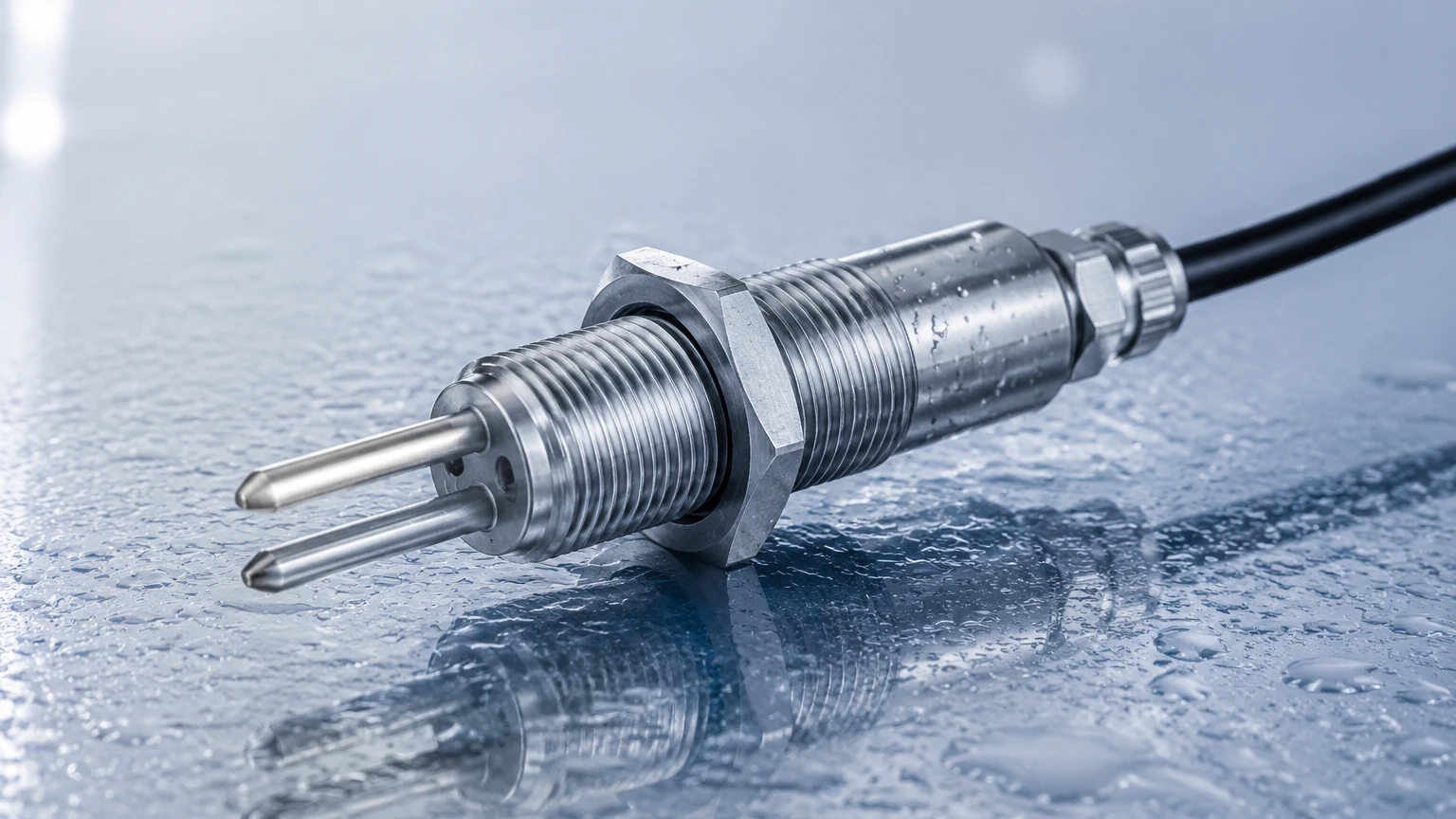
The term (L/A) is referred to as the "cell constant" (K). A resistivity sensor with a precisely defined cell constant allows the transmitter to convert raw resistance data into a standardized resistivity value, typically expressed in Megohm-centimeters (MΩ·cm).
Temperature Compensation
Resistivity is highly sensitive to temperature fluctuations. As the temperature of water increases, the mobility of ions increases, which decreases resistivity even if the actual ion concentration remains the same. Most industrial resistivity sensors include an integrated Resistance Temperature Detector (RTD), such as a Pt100 or Pt1000, to provide real-time temperature data. The transmitter then applies a compensation algorithm to normalize the reading to a reference temperature, usually 25°C (77°F). This ensures that the data reflects the actual purity of the liquid rather than thermal variations.
Key Applications in Process Industries
A resistivity sensor is primarily utilized in applications where water purity is extreme. In these environments, even trace amounts of dissolved solids or ionic contaminants can lead to catastrophic failure or product defects.
1. Semiconductor and Electronics Manufacturing
Semiconductor fabrication requires Ultrapure Water (UPW) for cleaning silicon wafers. Any ionic contamination can alter the electrical properties of the microchips. In this sector, resistivity sensors are used to ensure the water reaches the theoretical limit of absolute purity, which is approximately 18.2 MΩ·cm at 25°C.
2. Pharmaceutical and Biotechnology
Water for Injection (WFI) and purified water used in drug formulation must meet strict pharmacopeia standards (such as USP <645>). Resistivity sensors provide continuous monitoring to verify that ion exchange or Reverse Osmosis (RO) systems are functioning correctly, preventing the release of sub-standard batches.
3. Power Generation
In high-pressure boiler systems, the presence of dissolved minerals can lead to scaling and corrosion of turbine blades and boiler tubes. Resistivity sensors monitor the condensate and feed water purity. If resistivity drops, it indicates a leak in the condenser or a failure in the demineralization plant, allowing operators to take corrective action before equipment damage occurs.
Selection Criteria for Resistivity Sensors
Choosing the right resistivity sensor requires an evaluation of the process environment and the required measurement range. Unlike level meters, which may be non-contact, resistivity sensors are primary elements that must be in direct contact with the fluid.
Electrode Material
The material of the electrodes must be chemically compatible with the process fluid and resistant to polarization. Common materials include:
| Material | Application | Advantages |
| :— | :— | :— |
| 316L Stainless Steel | General industrial water, RO systems | Durable, cost-effective, corrosion-resistant. |
| Titanium | Ultrapure water, mildly corrosive media | Excellent chemical resistance, high precision. |
| Graphite | High-conductivity/Low-resistivity fluids | Resistant to fouling, suitable for harsh chemicals. |
| Monel/Hastelloy | Highly corrosive or saline environments | Superior resistance to pitting and stress corrosion. |
| Platinum | Laboratory and high-precision standards | Extremely stable, inert, used for calibration. |
Cell Constant Selection
The cell constant (K) determines the sensor's sensitivity range. For high-resistivity (ultrapure) water, a low cell constant (e.g., K=0.01 cm⁻¹ or K=0.1 cm⁻¹) is required to ensure accurate measurement of very low ion concentrations. Conversely, for liquids with higher conductivity, a higher cell constant (e.g., K=1.0 cm⁻¹ or higher) is used.
Physical Configuration
* Insertion Sensors: Designed for direct installation into pipes or tank walls via NPT or G threads.
* Flow-Through Sensors: Integrated into a small bypass line or a dedicated flow cell, ideal for low-flow applications where bubbles must be minimized.
* Submersible Sensors: Used in open tanks or sumps, though less common for high-purity resistivity applications.
Installation Considerations and Best Practices
To maintain the accuracy of a resistivity sensor, proper installation is paramount. Because the sensor measures electrical properties at a micro-scale, environmental factors can easily distort the readings.
1. Eliminate Air Pockets: The sensor electrodes must be completely submerged in the liquid. Air bubbles trapped against the electrode surface will act as insulators, leading to erroneously high resistivity readings. Installing sensors in a vertical pipe with upward flow is a common strategy to prevent air entrapment.
2. Avoid Flow Stagnation: Resistivity sensors should be placed in areas with constant flow to ensure the sample is representative of the process. In ultrapure water systems, stagnant water can quickly leach ions from pipe walls, leading to localized drops in resistivity.
3. Proper Grounding: Electrical noise from pumps, motors, or variable frequency drives (VFDs) can interfere with the low-voltage signals produced by the sensor. Using shielded cables and ensuring the process piping is properly grounded is essential for signal integrity.
4. Insertion Depth: The sensor should be inserted deep enough into the flow stream to avoid "wall effects," where the proximity of the pipe wall influences the electric field between the electrodes.
Limitations and Potential Risks
While highly accurate, resistivity sensors have specific limitations that engineers must account for in their system design:
* Fouling and Scaling: If the liquid contains oils, biological growth, or precipitating minerals, a film can form on the electrodes. This increases the measured resistance, leading to a false high-resistivity reading. Regular cleaning is required in non-ultrapure applications.
* Non-Ionic Contaminants: A resistivity sensor only detects ionic (electrically charged) impurities. It cannot detect non-ionic contaminants such as silica, organics, or bacteria. Therefore, resistivity should be used alongside Total Organic Carbon (TOC) analyzers for a complete purity profile.
* Cable Length Constraints: Because the sensor measures high resistance, the capacitance and resistance of the connecting cable can influence the reading. It is often recommended to use a transmitter located close to the sensor or to utilize digital sensors (such as those using RS485/Modbus) that convert the signal at the sensor head.
Maintenance and Calibration Procedures
To ensure long-term reliability, a resistivity sensor requires periodic verification. Unlike a radar level meter which might operate for years without drift, the electrochemical nature of resistivity measurement necessitates a maintenance schedule.
Cleaning
Electrodes should be cleaned with a non-abrasive detergent or a mild acid (depending on the contaminant) to remove films. After cleaning, the sensor must be thoroughly rinsed with deionized water to remove any residues that could skew the next measurement.
Calibration
Calibration is typically performed using one of two methods:
1. Comparison Method: Comparing the process sensor's reading against a calibrated portable "master" meter in the same flow stream.
2. Resistor Substitution: Using high-precision resistors to simulate the liquid's resistance. This verifies the transmitter's electronics but does not account for the physical condition of the sensor electrodes or the cell constant accuracy.
In high-purity applications, standard solutions (conductivity standards) are often impractical because they are easily contaminated by atmospheric CO2 once opened, which rapidly changes their resistivity. In these cases, electronic calibration and comparison to a NIST-traceable reference meter are preferred.
Frequently Asked Questions (FAQs)
Q: What is the difference between a resistivity sensor and a conductivity sensor?
A: Mechanically, they are often identical. The difference lies in the output and the application. Resistivity is the reciprocal of conductivity (Resistivity = 1 / Conductivity). Resistivity is typically used for very pure water (MΩ·cm), while conductivity is used for water with more dissolved solids (µS/cm or mS/cm).
Q: Can a resistivity sensor be used in saltwater?
A: It is not recommended. Saltwater has very high conductivity (low resistivity). The electrodes would polarize quickly, and the measurement would be outside the sensitive range of a standard resistivity sensor. A toroidal (inductive) conductivity sensor is better suited for high-salinity environments.
Q: How often should I calibrate my resistivity sensor?
A: In ultrapure water applications, a semi-annual or annual verification is usually sufficient. In more demanding industrial processes where fouling is possible, monthly checks may be necessary.
Q: Does pipe material affect the sensor?
A: In plastic piping, there is little interference. In metal piping, if the sensor is installed too close to the pipe wall, it can affect the cell constant. Always follow the manufacturer’s minimum clearance specifications.
Conclusion
The resistivity sensor is an indispensable tool for industries where liquid purity is a primary driver of quality and safety. By understanding the relationship between ion concentration and electrical resistance, and by selecting the appropriate electrode materials and cell constants, engineers can maintain tight control over their water treatment processes.
When designing a complete monitoring solution, it is important to integrate resistivity data with other process variables. For a comprehensive range of industrial measurement instruments, including those for level, flow, and pressure, visit the Main Page to explore professional-grade hardware designed for modern industrial automation. Proper selection, installation, and maintenance of these sensors ensure that high-purity systems remain within specification, protecting both equipment and the final product.