Mag Meter Flow Meter
Mag Meter Flow Meter
In the landscape of industrial process control, the electromagnetic flow meter—commonly referred to as a mag meter flow meter—stands as a cornerstone technology for measuring the volumetric flow rate of conductive liquids. Unlike mechanical flow meters that rely on moving parts like turbines or gears, the mag meter utilizes electromagnetic properties to provide highly accurate, obstruction-free measurements. This article provides a comprehensive technical reference for engineers and plant managers on the principles, selection, and application of mag meter technology in modern industrial environments.
Measurement Principle: Faraday’s Law of Induction
Before evaluating specific models or installation sites, it is essential to understand the physics governing the mag meter flow meter. The operation is based on Faraday’s Law of Electromagnetic Induction, which states that a voltage will be induced when a conductor moves through a magnetic field.
In the context of a flow meter:
1. The Conductor: The conductive process liquid flowing through the pipe acts as the moving conductor.
2. The Magnetic Field: A pair of electromagnetic coils located on the outside of the flow tube generates a constant magnetic field ($B$) across the pipe cross-section.
3. Induced Voltage: As the liquid moves at a certain velocity ($v$) through the magnetic field, a voltage ($E$) is generated. This voltage is picked up by two electrodes mounted on opposite sides of the pipe wall.
The relationship is expressed by the formula:
$E = B \cdot v \cdot D$
Where:
* $E$ is the induced voltage (proportional to velocity).
* $B$ is the magnetic field strength.
* $v$ is the average velocity of the liquid.
* $D$ is the conductor length (which corresponds to the internal diameter of the pipe).
Because the magnetic field strength and the pipe diameter are constants, the induced voltage is directly and linearly proportional to the fluid velocity. The transmitter then converts this voltage signal into a standardized output, such as 4-20mA, pulse, or a digital protocol like Modbus or HART. For comprehensive process control, integrating these flow data points with reliable Main Page instrumentation ensures total system visibility.
Key Components of a Mag Meter
A standard mag meter flow meter consists of two primary elements: the primary device (the flow tube installed in the pipeline) and the secondary device (the electronic transmitter).
The Flow Tube
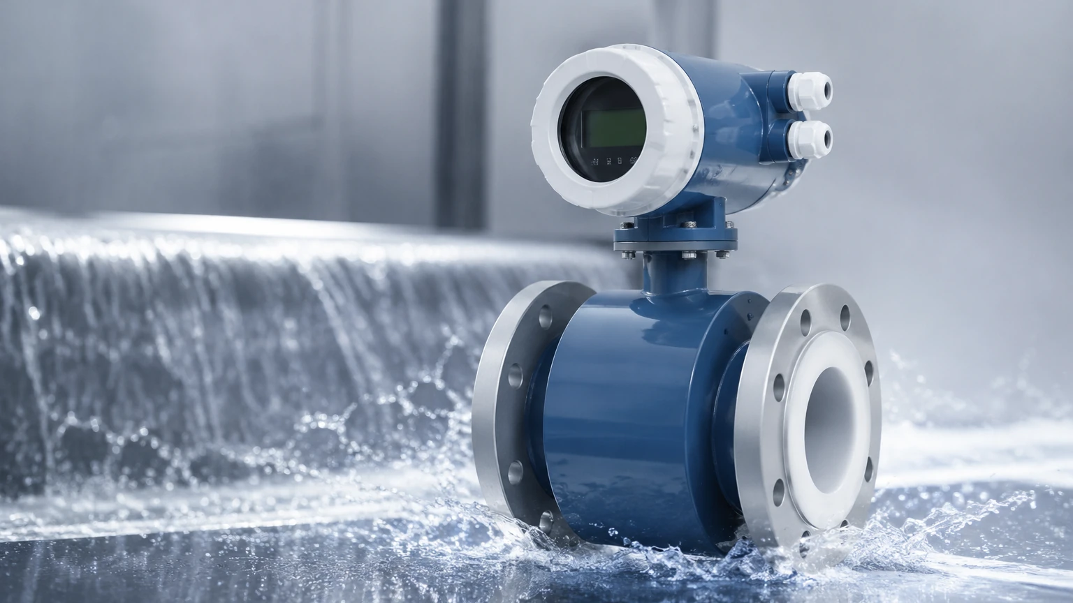
The flow tube is a non-magnetic section of pipe, typically lined with an insulating material to prevent the induced voltage from shorting into the pipe wall. It contains the electromagnetic coils and the sensing electrodes. Because there are no internal obstructions, the pressure drop across a mag meter is virtually zero, making it highly energy-efficient.
The Transmitter
The transmitter provides the excitation current to the coils and processes the microvolt-level signal from the electrodes. Modern transmitters include advanced diagnostics, such as empty pipe detection, electrode fouling alerts, and bi-directional flow measurement capabilities.
Selection Criteria and Technical Specifications
Choosing the correct mag meter flow meter requires a detailed analysis of the process fluid and the mechanical environment. The following factors are critical for a successful specification.
Fluid Conductivity
The most fundamental requirement for a mag meter is that the fluid must be electrically conductive. Most industrial mag meters require a minimum conductivity of 5 μS/cm (microsiemens per centimeter). While this covers most acids, bases, slurries, and water-based liquids, it excludes hydrocarbons, distilled water, and gases.
Liner and Electrode Materials
Since the liner and electrodes are the only parts in contact with the process media, material compatibility is paramount.
| Material Category | Common Options | Typical Applications |
| :— | :— | :— |
| Liner Material | PTFE (Teflon) | Highly corrosive chemicals, high temperatures. |
| | PFA | Similar to PTFE but better for vacuum conditions. |
| | Hard/Soft Rubber | Water treatment, non-corrosive fluids. |
| | Polyurethane | Abrasive slurries, mining applications. |
| Electrode Material | Stainless Steel 316L | Standard water and mild chemical use. |
| | Hastelloy C | Severe chemical corrosion resistance. |
| | Tantalum | Highly aggressive acids (e.g., Hydrochloric). |
| | Platinum-Iridium | Extreme chemical inertness. |
Accuracy and Rangeability
Mag meters typically offer high accuracy, often ranging from ±0.2% to ±0.5% of the flow rate. They also feature excellent turndown ratios (rangeability), often exceeding 100:1, allowing them to measure both peak flows and low-flow conditions accurately.
Installation Considerations
Proper installation is vital to maintain the accuracy and longevity of a mag meter flow meter. Even the most advanced meter will fail to perform if hydraulic conditions are ignored.
Straight Pipe Runs
To ensure a stable flow profile, mag meters require a specific amount of straight pipe upstream and downstream of the sensor. The general rule of thumb is:
* Upstream: 5 x Pipe Diameter (5D)
* Downstream: 2 x Pipe Diameter (2D)
If there are significant disturbances like pumps or partially open valves, the upstream requirement may increase to 10D.
Pipe Orientation and Filling
The pipe must be completely full for the mag meter to read accurately.
* Vertical Installation: The preferred orientation is vertical with the flow moving upward. This ensures the pipe remains full and prevents air bubbles from collecting at the electrodes.
* Horizontal Installation: If installed horizontally, the electrode axis must be horizontal (at the 3 o'clock and 9 o'clock positions). This prevents air bubbles at the top or sediment at the bottom from interfering with the signal.
Grounding
Since the induced voltage is often in the millivolt range, electrical noise can easily distort the signal. Proper grounding is essential. If the pipeline is made of non-conductive material (like PVC or lined pipe), grounding rings must be installed to provide a reference point for the fluid potential.
Practical Selection Table for Industrial Applications
| Industry | Fluid Type | Recommended Liner | Recommended Electrode |
| :— | :— | :— | :— |
| Water & Wastewater | Potable water, sewage | Hard Rubber / EPDM | SS316L |
| Chemical Processing | Sulfuric Acid, Caustics | PTFE / PFA | Tantalum / Hastelloy |
| Mining & Pulp | Ore slurries, paper pulp | Polyurethane / Ceramic | Hastelloy C |
| Food & Beverage | Juice, milk, beer | PFA (FDA approved) | SS316L (Polished) |
Limitations and Risks
While highly versatile, the mag meter flow meter has specific limitations that engineers must account for:
1. Conductivity Threshold: As mentioned, non-conductive fluids like oils or demineralized water cannot be measured.
2. Vacuum Conditions: Some liners, particularly PTFE, can collapse or peel away from the tube wall under vacuum conditions if not properly bonded or if PFA is not used instead.
3. Temperature Limits: The maximum temperature is limited by the liner material, typically capped at 150°C to 180°C (302°F to 356°F) for high-end PFA liners.
4. Coating and Scaling: If the process fluid tends to deposit scales or coatings (like calcium buildup), the electrodes can become insulated, leading to signal loss. In these cases, ultrasonic electrode cleaning or removable electrodes may be required.
Comparison with Other Flow Technologies
To understand why a mag meter flow meter might be preferred over alternatives, consider this comparison:
* Vs. Ultrasonic (Transit Time): Mag meters are generally more accurate for fluids with high solids content (slurries), whereas ultrasonic meters are preferred for non-conductive fluids or clamp-on applications.
* Vs. Vortex: Vortex meters are excellent for steam and gas but have a high "cut-off" velocity, meaning they cannot measure very low flow rates where a mag meter excels.
* Vs. Differential Pressure (Orifice Plate): Mag meters have no pressure drop and no moving parts, significantly reducing long-term pumping costs and maintenance compared to DP meters.
Maintenance and Troubleshooting
Because there are no moving parts to wear out, maintenance for a mag meter flow meter is minimal. However, periodic checks are recommended:
* Zero-Point Check: Periodically check the zero-flow reading under full-pipe, zero-velocity conditions.
* Insulation Resistance: Testing the resistance between the electrodes and the housing can identify liner leaks or electrode fouling.
* Transmitter Calibration: While the flow tube is stable, the electronic transmitter should be verified using a signal simulator to ensure the output electronics have not drifted.
Frequently Asked Questions (FAQ)
Q: Can a mag meter measure flow in both directions?
A: Yes, most modern mag meters are bi-directional and can provide separate totalizers for forward and reverse flow.
Q: What happens if the pipe is only partially full?
A: A standard mag meter will provide an inaccurate, usually erratic reading if the pipe is not full. For partially filled pipes, specialized "partially filled pipe" mag meters with additional electrodes are required.
Q: Does fluid viscosity affect the accuracy?
A: No. One of the primary advantages of the mag meter flow meter is that it is independent of viscosity, density, and pressure, provided the flow remains relatively turbulent or transitional.
Q: How long do mag meters typically last?
A: In non-corrosive water applications, it is not uncommon for a mag meter to have a service life exceeding 20 years. In abrasive or highly corrosive chemical service, the lifespan depends entirely on the correct selection of liner and electrode materials.
Conclusion
The mag meter flow meter remains a preferred choice for industrial liquid measurement due to its accuracy, lack of pressure drop, and minimal maintenance requirements. By carefully matching liner and electrode materials to the process media and adhering to strict installation guidelines regarding straight runs and grounding, users can achieve highly reliable flow data. For organizations seeking to optimize their fluid handling and storage systems, pairing these flow solutions with robust Main Page level measurement tools provides a complete picture of process efficiency and inventory control.