Coriolis Flow Meters
Coriolis Flow Meters
In the landscape of industrial process control, the ability to measure mass flow directly—rather than inferring it from volume—represents a significant leap in accuracy and reliability. Coriolis flow meters have emerged as the gold standard for high-precision applications across the chemical, oil and gas, and food and beverage sectors. Unlike volumetric flow meters, which require compensation for temperature and pressure to calculate mass, Coriolis technology leverages the physical properties of motion to provide a direct mass reading. This article explores the fundamental principles, selection criteria, and practical installation requirements of Coriolis flow meters, particularly as they relate to comprehensive fluid management systems alongside level measurement technologies.
The Physics of Coriolis Measurement
To effectively implement Coriolis flow meters, it is essential to understand the underlying physical phenomenon known as the Coriolis effect. In an industrial meter, this effect is harnessed by inducing vibration in one or more flow tubes through which the process fluid passes.
The Coriolis Effect and Phase Shift
When a fluid flows through a vibrating tube, it is subjected to Coriolis acceleration. As the fluid moves toward the point of maximum vibration amplitude (the center of the tube bend), it resists being accelerated upward and pushes down on the tube. Conversely, as the fluid moves away from the center toward the exit, it resists the deceleration and pushes up against the tube.
This creates a twisting motion or a "phase shift" between the inlet and outlet sides of the tube. Electromagnetic sensors located at the inlet and outlet sections record this vibration. When there is no flow, the two sine waves produced by the sensors are in phase. As mass flow increases, the degree of twist increases, causing a measurable time delay (delta-T) between the two signals. This time delay is directly proportional to the mass flow rate.
Multi-Variable Data Acquisition
One of the primary advantages of Coriolis flow meters is their ability to measure multiple process variables simultaneously:
1. Mass Flow: Derived from the phase shift/time delay.
2. Density: Derived from the resonant frequency of the tube vibration. A denser fluid increases the mass of the tube system, lowering the vibration frequency.
3. Temperature: Measured via an internal RTD (Resistance Temperature Detector) to compensate for changes in tube elasticity and provide process data.
By combining these three variables, the meter can also calculate volumetric flow and concentration (such as Brix or Plato scales), making it an exceptionally versatile instrument for complex industrial processes.
Why Choose Coriolis Flow Meters?
While the initial capital expenditure for Coriolis technology is typically higher than for electromagnetic or ultrasonic meters, the long-term value is often found in reduced maintenance and superior accuracy.
Unmatched Accuracy
Coriolis meters typically offer mass flow accuracy of ±0.1% or better. Because they measure mass, they are immune to changes in fluid viscosity, density, and conductivity. This makes them ideal for applications where the fluid composition may vary or where high-value fluids require precise custody transfer.
Minimal Maintenance
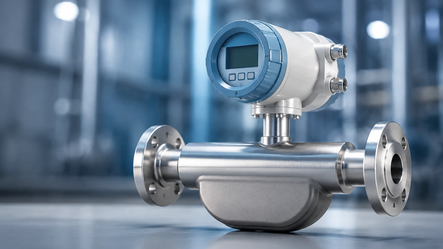
Most Coriolis designs have no moving parts in the traditional sense (no bearings, gears, or impellers). While the tubes vibrate, the mechanical stress is kept well within the fatigue limits of the materials (typically stainless steel, Hastelloy, or Tantalum). This results in a long service life with minimal drift in calibration compared to mechanical meters.
Integration with Level Measurement
In many industrial setups, flow meters work in tandem with level measurement instruments. While a radar level meter or ultrasonic sensor provides the current volume of a vessel, the Coriolis flow meter provides the precise mass of the material entering or leaving that vessel. This dual-data approach is critical for mass balance calculations, leak detection, and ensuring that inventory records match physical stock. For engineers looking to optimize these systems, reviewing comprehensive product options and application support on the Main Page can help in selecting the right combination of flow and level technologies.
Practical Selection Table
Choosing the right meter requires balancing performance requirements with fluid characteristics. The following table provides a general guideline for selecting Coriolis flow meters based on common industrial parameters.
| Application | Fluid Type | Typical Tube Design | Accuracy Requirements | Key Consideration |
| :— | :— | :— | :— | :— |
| Chemical Dosing | High Viscosity | Single Straight Tube | ±0.2% | Pressure drop & cleaning |
| Custody Transfer | Hydrocarbons | Dual U-Tube | ±0.05% to ±0.1% | Repeatability & Certification |
| Food & Beverage | Slurries/Dairy | Polished Straight Tube | ±0.1% | CIP/SIP compatibility |
| Gas Measurement | High Pressure Gas | Dual U-Tube | ±0.5% | Gas density at operating P/T |
| Sanitary Processes | Pharmaceutical | Self-Draining Curved | ±0.1% | Surface finish (Ra < 0.8 µm) |
Installation Considerations
Proper installation is the most critical factor in ensuring the theoretical accuracy of a Coriolis meter is achieved in the field. Unlike many other flow technologies, Coriolis meters do not require long straight runs of pipe upstream or downstream. However, they are sensitive to mechanical vibration and mounting stress.
1. Mounting and Support
The meter must be rigidly supported to prevent external pipe vibrations from interfering with the internal tube frequency. It is recommended to support the piping on both the inlet and outlet sides as close to the meter flanges as possible. The meter should never be used to support the weight of the piping.
2. Orientation
* Liquid Service: The preferred orientation is usually "tubes down" (for U-tube designs) to ensure the tubes remain full and to prevent gas bubbles from being trapped.
* Gas Service: The preferred orientation is "tubes up" to prevent condensate or liquids from collecting in the tubes.
* Slurry Service: Vertical installation with upward flow is often recommended to prevent solids from settling and to ensure the meter remains self-draining.
3. Zero Calibration
Once installed and under process conditions (full of fluid, at operating temperature and pressure), a "zero trim" or zero calibration must be performed. This should be done with the flow completely stopped using isolation valves, ensuring there is no leakage. This step accounts for any installation-induced stresses on the sensor tubes.
4. Pressure Drop
Because Coriolis meters often involve a reduction in pipe diameter or a split into two smaller tubes, the pressure drop (measured in bar or kPa) can be significant, especially with high-viscosity fluids. Engineers must verify that the available system pressure is sufficient to overcome the meter's pressure drop at maximum flow rates.
Limitations and Risks
Despite their versatility, Coriolis flow meters are not a universal solution for every application. Understanding their limitations is key to avoiding costly project failures.
* Entrained Gas: Small amounts of gas in a liquid stream (slug flow) can dampen the tube vibration, leading to measurement errors or the meter "stalling." While modern digital signal processing has improved performance in aerated fluids, high gas fractions remain a challenge.
* Initial Cost: For large pipe sizes (above 200 mm or 8 inches), the cost and physical weight of a Coriolis meter increase exponentially. In these cases, other technologies like ultrasonic or electromagnetic meters may be more cost-effective if mass flow is not strictly required.
* Material Compatibility: The thin-walled tubes of a Coriolis meter are susceptible to corrosion and erosion. Selecting the correct metallurgy is vital; for example, Tantalum may be required for highly corrosive acids where standard 316L stainless steel would fail.
* Size and Weight: High-capacity U-tube meters can be extremely heavy and bulky, requiring specialized lifting equipment and significant space in the piping layout.
Frequently Asked Questions (FAQs)
Q: Do Coriolis flow meters work on steam?
A: Generally, no. While they can measure gases, the high velocity and low density of steam often result in a pressure drop that is too high for practical measurement. Vortex meters are typically preferred for steam applications.
Q: How often should a Coriolis meter be calibrated?
A: While the electronics and sensors are stable, many regulated industries (like Oil & Gas) require annual or biennial calibration. For non-regulated processes, many users rely on internal diagnostics and only recalibrate if the "meter verification" tools indicate a shift in tube integrity.
Q: Can I use a Coriolis meter for bidirectional flow?
A: Yes, Coriolis meters are inherently bidirectional. They can measure flow in both directions and provide separate totals for forward and reverse flow, which is useful in loading/unloading applications.
Q: What is the maximum temperature a Coriolis meter can handle?
A: Standard models typically handle up to 200°C (392°F), but specialized high-temperature versions are available that can operate at up to 350°C (662°F) using remote electronics to protect the transmitter from heat.
Conclusion
Coriolis flow meters represent the pinnacle of flow measurement technology, providing direct mass, density, and temperature data with exceptional precision. For industrial operators, the transition to Coriolis technology often results in tighter process control, improved product quality, and more accurate inventory management. When integrated into a broader instrumentation strategy—including robust level measurement solutions—these meters provide the data necessary for sophisticated automation and efficiency.
By following strict installation guidelines and carefully matching the meter material to the process fluid, engineers can ensure long-term reliability. For those in the planning stages of a new facility or upgrading existing process lines, exploring the technical specifications and support available through the Main Page is a recommended next step to ensure the selected instrumentation meets the specific demands of the application.