Endress Hauser Houston
Endress Hauser Houston
Houston, Texas, serves as the primary hub for the global energy, petrochemical, and water treatment sectors. For engineers and procurement specialists operating in this industrial landscape, selecting the right level measurement instrumentation is a critical factor in maintaining plant safety, efficiency, and regulatory compliance. Many organizations look toward established regional presences, such as Endress Hauser Houston, to support their complex process requirements. However, a successful implementation requires a deep understanding of measurement physics, application-specific constraints, and the technical criteria that differentiate various sensing technologies.
This guide provides a comprehensive technical overview of level measurement principles, selection strategies for the Gulf Coast industrial environment, and practical installation considerations for professional engineers.
Fundamental Measurement Principles
Before selecting a specific instrument or engaging with local service providers, it is essential to understand how different technologies interact with the process medium. Level measurement is generally categorized into continuous measurement and point level detection.
1. Radar Level Measurement (Time of Flight)
Radar technology, particularly Frequency Modulated Continuous Wave (FMCW), has become the industry standard for volatile and high-pressure applications common in Houston’s refineries.
* Free-Space Radar: These instruments emit high-frequency electromagnetic pulses (typically 26 GHz or 80 GHz). The time it takes for the pulse to travel to the surface and back is measured to calculate the distance. The 80 GHz radar is particularly effective in narrow tanks or vessels with internal obstructions because it produces a narrow beam angle, minimizing false reflections.
* Guided Wave Radar (GWR): This technology uses a physical probe (rod or cable) to guide the microwave pulse to the liquid surface. It is highly effective for low dielectric constant ($ε_r$) fluids and applications with heavy foam or turbulence, as the probe ensures the signal reaches the surface and returns reliably.
2. Ultrasonic Level Sensors
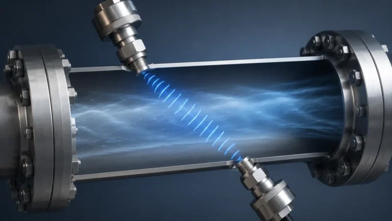
Ultrasonic sensors utilize mechanical sound waves. The transducer emits an ultrasonic pulse that reflects off the surface of the medium.
* Principle: The distance is calculated based on the speed of sound in air.
* Limitation: Because the speed of sound is affected by air temperature, humidity, and vapor composition, these sensors require integrated temperature compensation. In the high-humidity environment of Houston, ultrasonic sensors must be carefully calibrated to account for variations in the transmission medium.
3. Hydrostatic Level Measurement
Hydrostatic sensors measure the pressure exerted by a liquid column at a specific point.
* Formula: The level ($h$) is calculated using the formula $P = ρ × g × h$, where $P$ is pressure, $ρ$ is the density of the fluid, and $g$ is gravity.
* Application: This is a robust solution for vented tanks or deep wells. However, if the fluid density changes due to temperature fluctuations—a common occurrence in outdoor storage tanks in Texas—the accuracy of the measurement may drift unless density compensation is applied.
4. Magnetic Level Gauges (MLG)
For high-temperature and high-pressure applications where visual verification is required alongside electronic transmission, magnetic level gauges are preferred. They use a float containing a magnet that moves with the liquid level, actuating a series of external flags or a transmitter. This provides a physical, leak-proof barrier between the process and the observer.
Selection Criteria for Houston Industrial Applications
When evaluating solutions from providers like Endress Hauser Houston or Welk, engineers must match the technology to the specific environmental and process conditions of the Gulf Coast.
Environmental Factors
* Ambient Heat: Houston summers often see temperatures exceeding 38°C (100°F). Instrumentation electronics must be rated for high ambient temperatures, often requiring sunshades or remote-mounted electronics to prevent thermal drift or component failure.
* Corrosive Atmospheres: Proximity to the coast introduces salt spray, while the presence of H2S in oil and gas processing creates a corrosive environment. Housings should ideally be 316L stainless steel or high-grade coated aluminum.
* Humidity and Ingress: High humidity can lead to condensation within the housing. Instruments must have high Ingress Protection (IP67 or IP68) and dual-compartment housings to separate the wiring from the electronics.
Process Factors
* Dielectric Constant ($ε_r$): For radar applications, the reflectivity of the surface depends on the dielectric constant. Hydrocarbons often have low $ε_r$ (1.9 to 4.0), requiring high-sensitivity radar units.
* Agitation and Foam: If a tank has heavy agitation, a stilling well or guided wave radar may be necessary to maintain a stable signal.
Practical Selection Table
The following table serves as a baseline for comparing technologies based on typical industrial requirements.
| Technology | Typical Accuracy | Max Range (Approx.) | Media Type | Key Advantage | Major Limitation |
| :— | :— | :— | :— | :— | :— |
| 80 GHz Radar | ±1 mm (0.04 in) | 120 m (394 ft) | Liquids/Solids | Non-contact, high precision | High initial cost |
| Guided Wave Radar | ±2 mm (0.08 in) | 75 m (246 ft) | Liquids/Interface | Works in foam/low $ε_r$ | Probe fouling/buildup |
| Ultrasonic | ±0.2% of range | 15 m (49 ft) | Water/Wastewater | Cost-effective | Affected by vapor/wind |
| Hydrostatic | ±0.1% of span | Unlimited | Slurries/Liquids | Simple installation | Requires constant density |
| Magnetic Gauge | ±5 mm (0.2 in) | 6 m (20 ft) | Chemicals/Oil | Visual safety backup | Moving parts can wear |
Installation Considerations and Best Practices
Proper installation is as important as technology selection. Even the most advanced instrument from a top-tier provider will fail if the physical mounting is flawed.
1. Nozzle Geometry: For radar and ultrasonic sensors, the nozzle height and diameter must be considered. If the nozzle is too long or narrow, it can create internal reflections (ringing) that mask the true level signal.
2. Obstruction Avoidance: Ensure the signal beam path is clear of ladders, agitator blades, and heating coils. For radar, a "mapping" or "false echo suppression" procedure should be performed during commissioning to ignore these static reflections.
3. Mounting Angle: Sensors should typically be mounted perpendicular to the liquid surface. In solids applications, an aiming flange may be required to account for the angle of repose of the material.
4. Stilling Wells: In applications with extreme turbulence or heavy foam, installing the sensor inside a stilling well (a vertical pipe) can provide a calm surface for measurement. This is common in Houston’s large crude oil storage tanks.

Common Risks and Limitations
Engineers should be aware of the following risks when specifying level instrumentation:
* Vapor Space Attenuation: In high-pressure gas phases, the speed of radar signals can slightly change, or the signal can be attenuated. This is particularly relevant in high-pressure steam or CO2 applications.
* Coating and Buildup: In wastewater or viscous chemical applications, material can build up on the sensor face or probe. While some modern radars can "see through" thin coatings, heavy buildup will eventually cause a signal loss.
* Minimum Measuring Distance (Dead Zone): All Time-of-Flight sensors have a "dead zone" or "blocking distance" near the sensor face where measurements are not possible. This must be accounted for in the tank's overfill protection logic.
Frequently Asked Questions (FAQs)
Q: How does the Houston climate affect ultrasonic sensor accuracy?
A: High humidity and temperature fluctuations change the speed of sound. If the sensor does not have a reliable temperature probe or if there is a significant temperature gradient in the tank, the error can exceed 5-10%. In these cases, radar is often a more reliable choice.
Q: Can I use radar for interface measurement between oil and water?
A: Yes, Guided Wave Radar is the preferred technology for interface measurement. The signal reflects off the upper layer (oil) and continues through to reflect off the lower, more conductive layer (water).
Q: What certifications are required for instrumentation in Houston refineries?
A: Most installations require Class I, Div 1 or Div 2 (NEC/NFPA 70) certifications. Ensure any instrument sourced, whether from Welk or Endress Hauser Houston, carries the appropriate FM or UL markings for hazardous areas.
Q: Is 80 GHz radar always better than 26 GHz?
A: Not necessarily. While 80 GHz offers better focusing and smaller antennas, 26 GHz may be more robust in applications with heavy dust or very thick condensation on the antenna, as the longer wavelength can penetrate these obstacles more effectively.
Conclusion
Selecting level measurement instrumentation in the Houston area requires a balance of technical precision and environmental resilience. Whether you are managing a municipal water facility or a complex petrochemical refinery, understanding the physics of radar, ultrasonic, and hydrostatic measurement is the first step toward operational excellence. For those seeking a wider range of high-performance level measurement solutions tailored to these demanding environments, you can review product options and application support on our Main Page.
By following rigorous selection criteria and adhering to best practices in installation, Houston-based engineers can ensure their facilities operate with the highest levels of accuracy and safety.