Vega Sign
Vega Sign
In the complex landscape of industrial automation, the term "Vega sign" often refers to the critical interface between raw sensor data and actionable process information. In level measurement, a sensor is only as effective as the signal it produces and the system that interprets it. Whether managing a chemical storage farm or a municipal water treatment facility, understanding how signals are generated, transmitted, and displayed is fundamental to operational safety and efficiency. This guide explores the principles of signal processing, the technology behind remote indication, and the selection criteria for modern level measurement signaling systems.
The Role of Signal Indication in Industrial Level Measurement
At its core, a level measurement system consists of three primary stages: sensing, processing, and indication. The "sign" or signal produced by the sensor represents the physical distance or volume within a vessel. In modern industrial environments, this signal must be robust enough to travel long distances from the top of a tank to a control room, often through areas with high electromagnetic interference (EMI).
Signal indicators and controllers serve as the bridge in this process. They provide local visualization for field technicians and convert raw sensor outputs into standardized formats for Programmable Logic Controllers (PLCs) and Distributed Control Systems (DCS). For organizations looking to optimize their instrumentation architecture, reviewing various Main Page resources can provide insights into how different sensor types integrate with these signaling units.
Measurement Principles and Signal Conversion
Before a signal can be displayed or transmitted, it must be accurately generated. Different measurement technologies produce different types of raw data, which are then converted into a standardized "sign."
Radar and Ultrasonic Signal Processing
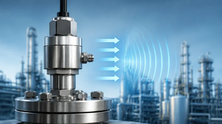
Radar level meters, such as those utilizing Frequency Modulated Continuous Wave (FMCW) or Pulse technology, emit electromagnetic waves toward the medium. The reflected echo is captured by the antenna. The internal electronics calculate the time-of-flight or frequency shift. This digital calculation is then converted into an output signal, typically a 4-20mA analog current loop or a digital fieldbus protocol.
Ultrasonic sensors operate on a similar principle but use sound waves. The challenge in both technologies is "signal noise." Obstructions like agitators, internal bracing, or foam can create false echoes. Advanced signal processing units use "False Signal Suppression" or "Echo Mapping" to ignore these artifacts and focus on the true level sign.
Hydrostatic and Pressure Signaling
Hydrostatic sensors measure the pressure exerted by a liquid column. This pressure is directly proportional to the level. The sensor's diaphragm converts mechanical pressure into an electrical signal. Because these sensors are often submerged or located at the bottom of a tank, the signal must be compensated for atmospheric pressure changes, usually via a capillary tube in the cable or a secondary reference sensor.
Types of Signal Transmission and Protocols
The "Vega sign" or signal is rarely just a simple voltage. In modern B2B applications, several protocols are used to ensure data integrity and provide diagnostic information.
1. 4-20mA Analog: The industry standard. It is highly resistant to noise and can power the sensor itself (two-wire system). A current of 4mA represents 0% level, while 20mA represents 100%.
2. HART (Highway Addressable Remote Transducer): This protocol superimposes a digital signal on top of the 4-20mA analog loop. It allows for bi-directional communication, enabling technicians to configure the sensor or view diagnostics without interrupting the analog signal.
3. Modbus RTU: A serial communication protocol used widely in industrial automation. It allows for multiple sensors to be connected on a single twisted-pair wire (multi-drop), significantly reducing wiring costs for large tank farms.
4. Profibus/Foundation Fieldbus: These are fully digital protocols used in complex plants. They provide high-speed data transmission and extensive device management capabilities.
Selection Criteria for Signal Processing Units
Choosing the right indicator or controller requires an evaluation of the application's specific needs. The following table provides a comparison of common signaling requirements:
| Feature | Local Display | Remote Controller | Fieldbus Gateway |
| :— | :— | :— | :— |
| Primary Purpose | On-site monitoring | Pump/Valve control | Data integration |
| Mounting | Directly on sensor | Control panel or wall | DIN rail in cabinet |
| Input Types | 4-20mA, HART | 4-20mA, Modbus | Multi-protocol |
| Relay Outputs | Usually none | 2 to 6 relays | Via PLC/DCS |
| Environment | IP66/67 required | IP20 (Indoor) or IP65 | IP20 |
Key Evaluation Factors
* Visibility: In outdoor installations, high-contrast LCDs or LED displays are necessary to ensure the sign is readable in direct sunlight.
* Power Supply: Does the unit need to provide power to the sensor (loop-powered), or does it have its own power source (AC/DC)?
* Hazardous Areas: If the sensor is in an explosive atmosphere (ATEX/IECEx zones), the signal indicator must also be rated for that zone or act as an intrinsic safety barrier.

Installation Considerations and Best Practices
Proper installation is critical to maintaining signal integrity. Even the most advanced radar level meter will fail if the signaling path is compromised.
Wiring and Shielding
Always use shielded twisted-pair cables for signal transmission. The shield should be grounded at only one end (usually the control room side) to prevent ground loops, which can introduce significant noise into the signal. For long distances—exceeding 500 meters (1,640 ft)—signal attenuation must be calculated to ensure the voltage drop does not fall below the sensor's minimum operating requirement.
Environmental Protection
Signal indicators located in the field are subject to temperature extremes, humidity, and UV radiation. Using sunshades and high-quality cable glands is essential. For hydrostatic transmitters, ensure the vent tube is protected by a moisture filter to prevent condensation from blocking the reference pressure path.
Configuration and Calibration
Most modern signaling units allow for "scaling." This means the 4-20mA sign can be mapped to specific units, such as liters, cubic meters, or feet. It is crucial to perform a "wet calibration" or a simulated signal check during commissioning to verify that the display matches the actual physical level in the tank.
Limitations and Common Risks
While signal technology has advanced, certain limitations remain:
* Signal Lag: In digital systems, there is a slight delay between the physical change in level and the update on the display. This must be accounted for in high-speed filling applications.
* Electromagnetic Interference (EMI): Large motors, VFDs (Variable Frequency Drives), and radio equipment can interfere with the signal. Proper separation of signal and power cables (at least 30cm or 12 inches) is a standard engineering requirement.
* Signal Clipping: If a sensor is misconfigured, it may reach 20mA before the tank is full, leading to dangerous overfill situations. Always set the "High-High" alarm slightly below the maximum signal output.
Frequently Asked Questions (FAQ)
Q: Can a signal indicator work with sensors from different manufacturers?
A: Yes, provided they use standardized protocols like 4-20mA or HART. Most universal controllers are designed to be brand-agnostic to allow for flexible system integration.
Q: What is the maximum distance for a 4-20mA sign?
A: Typically, up to 1,000 meters (3,280 ft) is achievable with high-quality 18 AWG wire, but this depends on the power supply voltage and the total loop resistance.
Q: How do I handle signals in a tank with heavy foam?
A: Foam can absorb the signal of ultrasonic and some radar sensors. In these cases, using a bypass pipe (stillpipe) or switching to a guided wave radar (GWR) can help maintain a stable signal sign.
Q: Is it better to use a digital or analog signal?
A: Analog (4-20mA) is simpler and easier to troubleshoot with a basic multimeter. Digital (Modbus/HART) provides more data, such as sensor health and temperature, but requires more specialized configuration tools.
Conclusion
The "Vega sign" represents more than just a number on a screen; it is the vital data stream that ensures industrial processes run safely and efficiently. By understanding the principles of signal generation, selecting the appropriate transmission protocols, and adhering to rigorous installation standards, engineers can build reliable level measurement systems. For those seeking specific hardware solutions or technical support for their level measurement projects, visiting the Main Page offers a gateway to professional-grade instrumentation and expertise.